


ZF0327 Friction Loss In Pipe Apparatus Didactic Education Equipment for School Lab Fluids Engineering Training Equipment
ZF0327 Friction Loss In Pipe Apparatus Didactic Education Equipment for School Lab Fluids Engineering Training Equipment Vocational Training Equipment for School Lab Training Equipment
- Description
- Inquiry
ZF0327 Friction Loss In Pipe Apparatus Didactic Education Equipment for School Lab Fluids Engineering Training Equipment
1. Equipment introduction
1.1 Overview
Pressure drop in a pipe is the loss of fluid pressure due to friction between fluid particles and conductor walls and obstructions in the pipe.
Pipe friction is one of the classic laboratory experiments and has always occupied a place in the practical teaching of fluid mechanics. The research results and underlying principles are important to aerospace, industrial and mechanical engineers alike.
Used to determine the coefficient of friction in pipes of various diameters and roughnesses, to study pressure losses in different types of valves and different fittings, and to compare different flow measurement methods.
General instructions
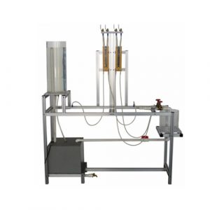
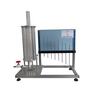
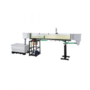
The device consists of six straight pipe sections made of different materials, with different diameters and roughness. Also included are various accessories for studying straight pipe losses, various types of valves (gate valves, ball valves, angle seat valves, etc.), pipe fittings (in-line filters, elbows, sudden widenings, contractions, etc.) and Measuring elements (venturi tube, pitot tube, orifice flow meter, etc.).
Some measuring elements, such as venturi tubes, pitot tubes, etc., are transparent to observe their function.
Different pipe sections, valves and pipe fittings include multiple pressure measuring points, with quick-connect devices to install pipes connected to corresponding pressure measuring devices.
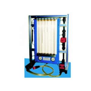
With this setup, friction pressure losses can be studied over a wide range of Reynolds numbers, covering laminar, transitional and turbulent flow regimes. Two water piezometers allow the study of pressure losses in laminar flow scenarios. Two Bourdon pressure gauges capture the pressure loss in turbulent flow conditions. It also includes a flow meter that measures the flow rate and compares it with measurements from the venturi and pitot tubes.
This unit requires a water supply system.
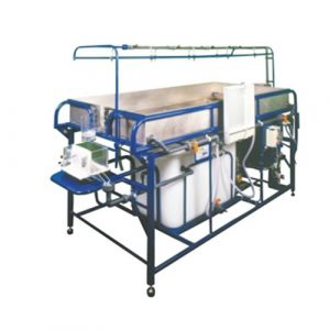
1.2 Features
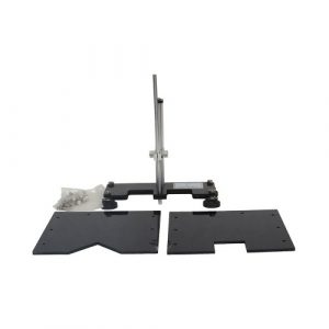
The main components include the meter and flow meter support structure.
A centrifugal pump draws water from a sump in the hydraulic bench (bring your own) and delivers it to the test tube. The flow meter installed in the pipe can be quickly and easily installed into the unit test area. These meters are available in a variety of different measuring principles and accuracy levels.
By using a water pressure gauge or two Bourdon-type pressure gauges, the pressure drop across each flow meter can be measured. Valves ensure rapid venting of all pressure gauge lines.
The water discharged from the flowmeter under test is collected in a volumetric tank (located within the hydraulic bench) where the flow rate can be absolutely determined. The tank is stepped to accommodate low or high flows and has a built-in wave baffle to reduce turbulence. A graduated level tube shows the water level. The water returns to the sump through the drain valve.
2. Technical parameters
Weight: about 150Kg
Working conditions: Temperature +5℃~+40℃, relative humidity <85% (25℃)
Size: about 2100mm * 845mm * 1270mm
3. Components list and detailed introduction
3.1 Main part
| No | Name |
| 1 | Stress testing module |
| 2 | Rough tube module with inner diameter 17mm |
| 3 | Rough tube module with inner diameter 23mm |
| 4 | 6.5mm inner diameter methacrylate tube module |
| 5 | Angle seat valve inner diameter 16.5mm smooth tube module |
| 6 | Gate valve inner diameter 26.6mm smooth tube module |
| 7 | Composite Pipe Module |
| 8 | T-type interface module |
| 9 | Rotameter module |
3.2 Equipment configuration list
| No | Name | Qty |
| Component 1 | Rotameter | 1 |
| Component 2 | Rough tube with inner diameter 17mm | 1 |
| Component 3 | Rough tube with inner diameter 23mm | 1 |
| Component 4 | 6.5mm inner diameter methacrylate tube | 1 |
| Component 5 | Angle seat valve | 1 |
| Component 6 | Inner diameter 16.5mm smooth tube | 1 |
| Component 7 | gate | 1 |
| Component 8 | Inner diameter 26.6mm smooth tube | 1 |
| Component 9 | mesh filter | 1 |
| Component 10 | Diaphragm valve | 2 |
| Component 11 | 25-40mm diameter variable pipe | 1 |
| Component 12 | pitot tube | 1 |
| Component 13 | Venturi tube | 1 |
| Component 14 | orifice plate | 1 |
| Component 15 | 40-25mm diameter variable tube | 1 |
| Component 16 | Parallel piping system | 1 |
| Component 17 | 90° elbow | 1 |
| Component 18 | T-joint | 15 |
| Component 19 | ball valve | 10 |
| Component 20 | 45° elbow | 2 |
| Component 21 | Bevel tee joint | 1 |
| Component 22 | Axial edged shock-resistant pressure gauge | 2 |
| Component 23 | hydraulic dispenser | 2 |
3.3 Accessories
| No | Name | Qty |
| 1 | CPC plastic quick connector external thread male | 2 |
| 2 | CPC plastic quick connector external thread female | 2 |
| 3 | Trachea 8-5.5 transparent | 7M |
4. Experiment list
Experiment 1 Stress Test Module Experiment
Experiment 2 Friction loss experiment of rough pipe with inner diameter 17mm
Experiment 3 Gate valve inner diameter 26.6mm smooth tube experiment
Experiment 4 Venturi tube experiment
Experiment 5 T-type interface module experiment
Related Products
ZM7101 Energy Losses in Bends Educational Equipment
ZM7101 Energy Losses in Bends Educational Equipment. Jinan Should Shine Didactic Equipment Co., Ltd. is company specialized in manufacture and trading Vocational Training Equipment,Didactic Equipment,Engineering Educational Equipment,Technical Teaching Equipment,for university,college,technical institution, polytechnics.Should Shine products has been exported to America,Asia,Europe,Africa, Australia.
ZM7105 Over Weirs Flow Measuring Teaching Equipment
ZM7105 Over Weirs Flow Measuring Teaching Equipment. Jinan Should Shine Didactic Equipment Co., Ltd. is company specialized in manufacture and trading Vocational Training Equipment,Didactic Equipment,Engineering Educational Equipment,Technical Teaching Equipment,for university,college,technical institution, polytechnics.Should Shine products has been exported to America,Asia,Europe,Africa, Australia.
ZM2142 Pipes Fluid Friction Venturi Method Hydraulic Bench Teaching Equipment
ZM2142 Pipes Fluid Friction Venturi Method Hydraulic Bench. Jinan Should Shine Didactic Equipment Co., Ltd. is company specialized in manufacture and trading Vocational Training Equipment,Didactic Equipment,Engineering Educational Equipment,Technical Teaching Equipment,for university,college,technical institution, polytechnics.Should Shine products has been exported to America,Asia,Europe,Africa, Australia.
ZM7113 Horizontal Flow From A Tank Didactic Equipment
ZM7113 Horizontal Flow From A Tank Didactic Equipment. Jinan Should Shine Didactic Equipment Co., Ltd. is company specialized in manufacture and trading Vocational Training Equipment,Didactic Equipment,Engineering Educational Equipment,Technical Teaching Equipment,for university,college,technical institution, polytechnics.Should Shine products has been exported to America,Asia,Europe,Africa, Australia.
ZM7107 Pressure Measurement Pressure Gauges Teaching Equipment
ZM7107 Pressure Measurement Pressure Gauges Teaching Equipment. Jinan Should Shine Didactic Equipment Co., Ltd. is company specialized in manufacture and trading Vocational Training Equipment,Didactic Equipment,Engineering Educational Equipment,Technical Teaching Equipment,for university,college,technical institution, polytechnics.Should Shine products has been exported to America,Asia,Europe,Africa, Australia.
SR-S12 Advanced Hydrology Study System Teaching Equipment
SR-S12 Advanced Hydrology Study System Teaching Equipment. Jinan Should Shine Didactic Equipment Co., Ltd. is company specialized in manufacture and trading Vocational Training Equipment,Didactic Equipment,Engineering Educational Equipment,Technical Teaching Equipment,for university,college,technical institution, polytechnics.Should Shine products has been exported to America,Asia,Europe,Africa, Australia.
ZM7102 Airflow System Teaching Equipment
ZM7102 Airflow System Teaching Equipment. Jinan Should Shine Didactic Equipment Co., Ltd. is company specialized in manufacture and trading Vocational Training Equipment,Didactic Equipment,Engineering Educational Equipment,Technical Teaching Equipment,for university,college,technical institution, polytechnics.Should Shine products has been exported to America,Asia,Europe,Africa, Australia.
ZM7111A Bernoulli’s Principle Demonstration Apparatus Teaching Equipment
ZM7111A Bernoulli’s Principle Demonstration Apparatus Teaching Equipment. Jinan Should Shine Didactic Equipment Co., Ltd. is company specialized in manufacture and trading Vocational Training Equipment,Didactic Equipment,Engineering Educational Equipment,Technical Teaching Equipment,for university,college,technical institution, polytechnics.Should Shine products has been exported to America,Asia,Europe,Africa, Australia.
ZM7103 Hydraulics Bench with Pump Educational Equipment
ZM7103 Hydraulics Bench with Pump Educational Equipment. Jinan Should Shine Didactic Equipment Co., Ltd. is company specialized in manufacture and trading Vocational Training Equipment,Didactic Equipment,Engineering Educational Equipment,Technical Teaching Equipment,for university,college,technical institution, polytechnics.Should Shine products has been exported to America,Asia,Europe,Africa, Australia.
ZM7110B Osborne Reynolds Trainer Teaching Equipment
ZM7110B Osborne Reynolds Trainer Teaching Equipment. Jinan Should Shine Didactic Equipment Co., Ltd. is company specialized in manufacture and trading Vocational Training Equipment,Didactic Equipment,Engineering Educational Equipment,Technical Teaching Equipment,for university,college,technical institution, polytechnics.Should Shine products has been exported to America,Asia,Europe,Africa, Australia.
-300x300.jpg)