- Description
- Inquiry
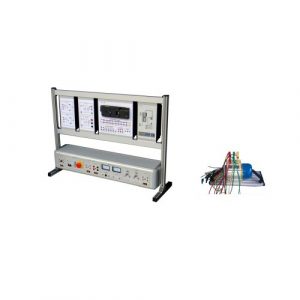
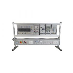
TB230621S46 EDA/SOPC Innovative Training Kit Educational Lab Equipment Electrical Engineering Laboratory Equipment
1. Overview
TB230621S46 open EDA technology basic experiment development system integrates multiple data processing, signal conversion, I/O interface, signal source and classic single-chip MCS51 system, suitable for
EDA technology experiment teaching, colleges and universities at all levels
Student electronic design competition, course design and graduation design, etc.
providing a good software and hardware environment for innovative development.
2. Performance characteristics
1) The system adopts the replaceable mode of the core board, which is configured according to the needs of users. The core board can be equipped with CPLD/FPGA devices from many famous international companies such as Altera, Lattice, Xilinx, etc., including the programming of CPLD/FPGA with different working voltages. , and the chip on the main system can be automatically identified without any jumper switching during programming, which is safe and reliable, and is suitable for students’ high-density experimental operations.
2) The system provides a variety of core chip operating voltages of 5V, 3.3V, 2.5V, and 1.8V.
3) All CPLD/FPGA resources on the core board of the system are open to users. With the cooperation of other peripheral modules, it can fully meet the design from simple digital circuits to complex digital systems.
4) With the support of configuration software, this system can simulate most of the on-site industrial control process, with vivid images and strong perceptual knowledge, which can enhance students’ learning interest and improve learning efficiency.
3. Technical indicators
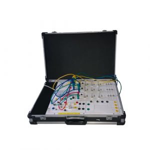
1) The training box is composed of an all-aluminum alloy box, a switching power supply and an integrated integrated motherboard.
2) Working power supply:
Input: AC220V±10%
Output: (1) DCV 5V/2.0A DC regulated power supply.
(2) DCV ±12V/0.5A DC regulated power supply.
3) Clock signal source: 24MHZ, 12MHZ, 6MHZ, 3MHZ, 1.5MHZ, 75OKHZ, 65536HZ32768HZ, 16834HZ, 8192HZ, 4096HZ, 1024HZ, 256HZ, 64HZ, 16HZ, 8HZ, 4HZ, 2HZ, 1HZ, 1/2H Z.
4) 12-bit LED display circuit
5) 8-bit second gear switch and its level indicating circuit
6) 8-bit key switch circuit
7) 8-bit dynamic scanning display circuit
8) A 4*4 keypad
9) 16*16 LED dot matrix display module
10) 128*64 LCD liquid crystal display module
11) Parallel A/D 0809 conversion module, serial A/D conversion TLC549
12) Parallel D/A 0832 conversion module, serial D/A conversion TLC5615
13) Electronic audio module
14) Four-phase stepper motor and DC motor control drive circuit
15) Keil microcontroller expansion circuit, with USB downloader.
16) Memory EPROM27256 (or E2PROM2864) circuit
17) One RS232 interface and one PS/2 (keyboard, mouse) interface
18) One VGA port
19) Waveform generator circuit
20) USB interface module
21) Analog level adjustment module
22) The core board is equipped with Altera’s EP1C12 device as standard (can be configured according to user needs), and it is equipped with a USB download cable.
4. Experimental project
Basic Digital System Design
1) Four-bit full adder
2) Four-bit parallel multiplier
3) BCD code adder
4) Design basic flip-flops
5) Design 74LS160 counter function module
6) Four-bit shift multiplier
7) English alphabet display circuit
8) Seven-person voting device
9) Gray code conversion circuit
10) Positive and negative pulse width numerical control modulation signal generator
11) Sequence detector
interface experiment
1) ADC0809 analog-to-digital conversion experiment
2) D/A converter DAC0832
3) Stepping motor control experiment
4) LED dot matrix display experiment
5) Keyboard extension experiment
6) Clock display experiment
7) LCD liquid crystal display (LCD)
8) VGA color bar signal generator
9) RS232 serial port experiment
10) PS/2 keyboard interface logic design
11) Serial D/A converter TLC5615
12) Serial AD converter TLC549
5. System configuration
One set of experiment box.
One core board module and one dedicated download line.
A set of system software and experimental instructions.
30 experimental wires.
One RS232 serial communication line.


-300x300.jpg)
