- Description
- Inquiry
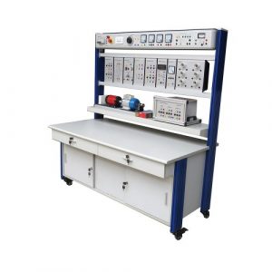
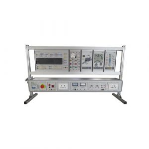
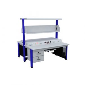
TB230621S04 Microwave and Antenna Integrated Training Kit Educational Equipment Electrical Engineering Lab Equipment
- Functional requirements
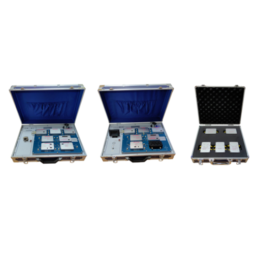
- The hardware part of the microwave technology comprehensive experiment box should include three parts: the sending system experiment box, the receiving system experiment box and the passive module experiment box.
- The experimental box should adopt a modular design. In order to prevent radiation, each microwave module should be shielded and protected by a metal shielding case.
- It should be able to carry out microwave transmission and reception of all TV signals (including video and sound signals), and the experimental platform should have its own camera and monitor.
★4. The input and output signals of each unit circuit of the experimental box should be set with switches for signal switching, so as to avoid frequent connection and disconnection during the experiment and facilitate testing.
- There should be independent test points before and after the circuit module of the experiment box. It adopts the SMA interface form and has the signal spectrum test function. The unit circuit test can be carried out independently without disassembling the cable.
★6. The transceiver system should be equipped with a digital modulation and demodulation module. The module needs to be integrated with a USB interface and can be connected to a PC for digital microwave communication system experiments.
- Both the sending and receiving equipment should be equipped with antenna brackets, and the angle of the antenna can be adjusted by rotating the antenna pole.
★8. The frequency setting of the microwave phase-locked loop module should support the dial for visual adjustment to facilitate students’ experiments.
- The passive module experiment box is used for module storage. It adopts an aluminum alloy frame structure. The module storage uses materials such as anti-static foam or sponge. The holes that can completely match the size of the module can be used to fix the module.
- Product configuration requirements:
1) The sending test box should include the following functional modules: audio and video modulation module, microwave phase-locked source, microwave up-conversion, voltage-controlled attenuator, power amplifier, microstrip bandpass filter, data transmission module, camera (fixed on the test box), antenna and antenna bracket, etc.;
2) The receiving experiment box should include the following functional modules: cavity filter module, microwave phase-locked source, low-noise amplifier, microwave down-conversion, audio and video demodulation module, Wilkson power divider, data transmission module, color monitor (fixed on the experiment box), antenna and antenna bracket, etc.;
3) The passive module experiment box includes the following functional modules: 50Ω transmission line module, λ/4 transmission line impedance transformation module, double branch directional coupler module, parallel line directional coupler module, lumped parameter LPF module.
4) Portable vector network analyzer: including 3G vector network analyzer portable equipment, standard microwave calibration parts (open circuit, short circuit, 50Ω standard load), microwave test cable and network analysis test software, the functional requirements are as follows:
(1) The SMA radio frequency interface should be used to facilitate the connection of various microwave devices under test.
(2) Frequency measurement range: 50KHz-3000MHz.
(3) Frequency accuracy: <0.5ppm.
(4) It adopts a full touch screen, and the TFT liquid crystal display has a viewing angle close to 180°, which will not hurt the eyes after long-term use. The operation interface menu supports switching between Chinese and English.
(5) Adopt compact design, small and portable size, customized 5000mAh super-large capacity lithium battery, long battery life, and extended charging interface.
(6) Supports the measurement of S parameters, including Smith chart, voltage standing wave ratio, phase-frequency diagram, amplitude-frequency diagram, group delay, polar coordinates, etc.; and provides a mark function, which can be moved on the screen to observe the measurement results.
★(7) Provide standard microwave calibration parts such as open circuit, short circuit and 50 standard load, which can be used as calibration work before experimental testing to make experimental test results more accurate.
(8) Supporting network analysis and test software is provided, which can be connected with network analyzer hardware equipment, extract hardware test data, and provide multi-icon display data, such as Smith, LogMag, Phase, VSWR of S11 and S21, and support software to cooperate with calibration operations.
- Technical index requirements
- Microwave phase-locked source
Output frequency Freq: 1970-2030MHz
Output power Power: 12dBm
- Microwave up-conversion
Intermediate frequency frequency range IF: DC-1.5GHz
Local oscillator & RF frequency range RF & LO: 1.5-4.5GHz
Frequency conversion loss IL: 8.5dB
- Voltage controlled attenuator
Frequency range Freq: 0.1-4GHz
Maximum attenuation Max Att: 27dB
Voltage standing wave ratio VSWR: <1.5
Control voltage Vc: 0~12V
- Power amplifier
Frequency range Freq: 1.9-2.1GHz
Gain: no less than 30dB
Voltage standing wave ratio VSWR: <1.5
- Microstrip bandpass filter
Passband frequency range Freq: 2010-2025MHz
Center frequency Fc: 2017.5MHz
- Cavity filter module
Frequency: 2030~2090MHz
Impedance: 50Ω
VSWR: ≤1.5
- Low noise amplifier
Frequency range Freq: 1.9-2.1GHz
Gain: 40dB
Voltage standing wave ratio VSWR: <1.5
- Microwave down conversion
Intermediate frequency frequency range IF: DC-1.5GHz
RF & local oscillator frequency range RF & LO: 1.5-4.5GHz
Frequency conversion loss IL: 8.5dB
- Wilkson Power Divider
Frequency Freq: 1.9-2.1GHz
Insertion loss IL: <1dB
Isolation ISO: >15dB
Voltage standing wave ratio VSWR: <1.5
- Double branch directional coupler
RF interface: SMA;
Coupling degree: 6dB±1dB;
Isolation: >20dB;
Standing wave ratio: <1.5;
Insertion loss: 0.5dB.
- Parallel line directional coupler
RF interface: SMA;
Coupling degree: 20dB±1dB;
Standing wave ratio: <1.5;
Insertion loss: 0.5dB.
- Experiment content requirements
Composition and testing of audio and video microwave transmission system, composition and testing of audio and video microwave receiving system, principle and test of voltage-controlled attenuator, principle and test of microstrip bandpass filter, principle and test of low noise amplifier, principle and test of power divider, principle and test of microwave phase-locked source, principle and test of microwave up-down conversion, principle and test of power amplifier, principle and test of microwave cavity filter, principle and test of 50Ω transmission line, principle and test of double branch directional coupler, principle and test of parallel linear directional coupler, Principle and test of lumped parameter low-pass filter, assembly and debugging of data microwave communication system.


