


- Description
- Inquiry
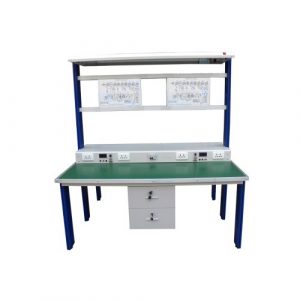
TB-240822-V-101 Electronics Package
Overview
This equipment is based on the professional qualification standards issued by the Ministry of Human Resources and Social Security, such as “Electronic Radio, Television and Communication Equipment Installer”, “Radio, Television and Communication Equipment Debugger”, “Electronic Special Equipment Installer”, “Radio Debugger”, “Semiconductor Discrete Devices and Integrated Circuit Assembly and Debugging”, etc. It is suitable for skill assessment and appraisal of related positions in the electronic communication industry. It can also be used for electronic technology foundation and design, single-chip microcomputer principle and application, embedded system and application, course teaching training, innovative design, various electronic technologies, etc.
General parameters
Power supply: single-phase three-wire AC220V±5% 50Hz/60Hz, 1.5kW
Safety protection: leakage protection, overcurrent protection
Electronic product implementation standard: IPC-A-610 F
Ambient temperature: -10~50℃
Relative temperature: ≤85%
Dimensions: The space occupied by the equipment when installed is not more than 6 square meters, and the overall height is not more than 2m
Product features
Learner recognition ability, targeted diagnostic training
A detailed and complete record of the contestant’s training process and results, a multi-dimensional comprehensive analysis, and an in-depth diagnostic analysis report are formed to provide guidance for the focus and direction of the next training.
The system’s automatic scoring can be used for both theoretical exams and practical operation assessments.
It can automatically score according to the contestant’s answers.
Data center management
Collect the data generated during the actual operation of the three major instruments and upload them to the server, receive and record data from the PCB status collector, station recorder, contestant-related information, etc.
PCB status acquisition
It can collect, process and display PCB status information. Relying on advanced lens tube technology, the system can maintain a stable state. It can centrally collect PCB sample data and provide high-quality PCB images to upload to the server for competition training and evaluation
Related knowledge and related skills
- Enable students to design electronic circuits according to the required PCB size and copper wire wiring
- Enable students to understand the demand for electronic products for commercial and non-commercial product repair and assembly
- Improve students’ skills in using electronic tools and measuring instruments
- Improve the quality of students’ welding technology during circuit and electronic design and assembly
- Train students to correctly use test instruments and other related electronic tools and equipment
- Improve students’ programming skills for microcontroller devices and other related products
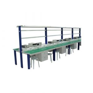
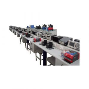
Equipment package
1 set of workbench
2200×1600 x1950 mm.
Aluminum frame, L-shaped, sheet metal structure
Desktop: 25mm thick fireproof high-density fiberboard
LED light shed (made of high-quality steel plate cold rolling process, surface electrostatic spraying, equipped with creative modern pcs-shaped LED ceiling lamp, floating table shape, full of science fiction)
Tool consumables net hanging board (fine steel plate heat dissipation)
1 set of functional integrated cabinet
Module:
1 power control module 1 AC socket module 1 oscilloscope module
1 functional signal generator module
1 DC power supply module
1 set of central controller
1 status light 1 workstation recorder 1 PCB status collector
1 set of tool cabinet
Cold-rolled steel plate surface electrostatic spraying
With universal wheels with brakes
4 drawers
1 set of training screen
1570x250x289 mm
Module:
Programmable DC power supply (CH1/CH2),
Rated output voltage: CH1/2: 0~36V (CH1/CH2)
CH3: 1.8V/2.5V/3.3V/5V, 0~6V, 2A,
CH4: USB 5V/2A
Minimum resolution 10mV/1mA
Output on/off
Overvoltage and overcurrent protection
Power-off memory
Keyboard lock, key tone
One-touch preset value
USB Device, RS-232, digital I/O interface
EBTN ultra-black bottom LCD
Power supply voltage: AC 100V/230V
Frequency: 50/60Hz
Programming/readback accuracy (25℃+5℃): voltage ≤0.1%+3mV current ≤0.5%+2mA
Ripple and noise: voltage ≤1mVms (5Hz~1MHz), current ≤3mArms
Temperature coefficient: voltage/current ≤300ppm/℃
Supports Virtual Instrument Architecture (VISA) standard communication interface, supports host computer monitoring instrument through VISA interface SDK, and exports fault records such as abnormal operation records such as short circuit and overcurrent. Software screenshots are required when bidding
Digital oscilloscope
Bandwidth not less than 120MHz, real-time sampling rate not less than 1GS
Analog channels not less than 4 (non-interleaved: each channel is sampled independently)
Memory depth per channel not less than 56Mpts (four channels are turned on at the same time), memory depth supports automatic mode and manual selection
Not less than 7-inch WVGA (800×480) TFT LCD screen, grayscale display not less than 256 levels (supports color temperature display)
Waveform capture rate not less than 600,000wfms/s, supports trigger output (Trigger Out) to verify waveform capture rate
Vertical deflection coefficient: 1mV/div~20V/div
Low background noise: <100uVrms
Time base range 5ns/div~50s/div
Support independent adjustment of each channel benchmark in time
Support addition, subtraction, multiplication, division, FFT, advanced operations (support formula editing), logical operations and other calculation functions
Standard trigger types: edge, pulse width, under amplitude, over amplitude, N edge delay, timeout, duration, establishment/hold, slope, video, code type
Support RS232/UART, I2C, LIN, SPI, CAN full memory hardware decoding
Support external network remote control Web control
Equipped with standard interfaces: USB Host, USB Device, LAN, EXTTrig, AUX Out (Trig OutPass/Fail)
Support logic analyzer module virtual instrument architecture (ViSA) standard
Support communication interface, support host computer to monitor instruments through ViSA interface SDk, export monitoring waveform data, capture all instrument screen images, which can be uploaded as the basis for assessment and scoring. Software screenshots must be provided when bidding.
Function/arbitrary waveform generator
Output waveform: sine wave, square wave, ramp/sawtooth wave, pulse wave, harmonic, noise, DC, expression, arbitrary wave
Output frequency range: sine wave: 1uHz~100MHz, square wave 1μHz~30MHz (optional)
Arbitrary wave: 1yHz~20MHz Ramp: 1uHz-20MHz
DDS technology, dual-channel independent output
Built-in 16th harmonic generator
Built-in high-precision, wide-band frequency meter with no less than 7 bits
Frequency range: 100mHz~200MHz
Output amplitude (high impedance): continuously adjustable, output amplitude error between 2mVpp~20Vpp is about ±1%
Vertical resolution: 16bit, sampling rate: 500MS/s
Dual channels output independently point by point at the same time
Maximum arbitrary wave length: 16Mpts
Analog digital modulation type: AM, FM, PM, ASK, FSK, PSK, BPSKQPSK, OSK, DSB-AM, PWM, SUM, QAM
Display: no less than 8-inch WVGA (800×480) TFT LCD screen, simultaneously displaying two-way frequency, amplitude and other information
USB Device, USB Host, LAN interface, support U disk storage and system upgrade
Support VirtualInstrument Architecture (SA) standard communication interface, supports the host computer to monitor the instrument through the VSA interface SDK, export dual-channel waveform data, capture all instrument screen images, which can be uploaded as the basis for assessment and scoring. Software screenshots are required when bidding.
Central controller
Embedded in the training screen panel as a training screen module, the central control system function is installed:
- Central call system: including the setting and display of workstations/competition items, intuitive display of countdown time, and control of the status of three-phase lights according to the competition or training status; according to the call mechanism defined by the national competition standard, call events include: questions/medical/equipment problems/going to the bathroom/applying for ratings/cancellation/completion, and the main screen response time after operating the call button shall not exceed 1 second; the number of calls/cancellations/completions will be automatically counted, and all operation records and time nodes will be displayed in a list format to facilitate query of operation records. The central system call system is compatible with the handheld call board and can exist at the same time or work independently.
- Central instrument management system: connects three instruments (oscilloscope, DC power supply, function signal generator) through the standard communication interface of virtual instrument architecture (VlSA), monitors instrument process data in real time, supports capturing screen images and waveform data of instruments such as oscilloscopes and function signal generators, monitors 3-way status data of DC power supply in real time, and has the function of recording fault information. The collected images and data can be uploaded to the server as the basis for scoring in competitions or assessments.
PCB status collector function: supports real-time preview and identification of cameras connected to USB or Ethernet interfaces, supports taking photos and uploading them to the server as the basis for scoring in competition assessments, and supports image magnification of not less than 20 times.
Workstation record management function: supports real-time preview and identification of cameras connected to USB or Ethernet interfaces, and the image resolution is not less than 1920*1080 pixels. The monitoring range includes the programming area of the electronic workbench, the training screen panel, the work surface, etc. The student activity area supports high-definition recording, manages recorded video files in a list, and can directly play videos or turn off playback; video files can be uploaded to the server as the scoring process for assessments: supports student information login verification, and uploads student information to the server for data association.
Equipment power monitoring function: The central software integrates power control and energy consumption monitoring functions, which can control multimedia power supplies, lighting switches, signal lights and other related hardware accessories in real time, monitor equipment power supply voltage/current/power and other parameters in real time, record equipment power usage and duration, voltage/current power, etc., and display the change curve in real time in the form of a chart.
Training screen-status light
Three-color light function: green light represents operation, yellow light represents warning, red light represents stop, and buzzer sounds
Training screen-station recorder
Contains monitoring cameras and recording software to record the movement trajectory, programming interface and related instrument operation process in the workstation. The recording software supports real-time preview of the screen and list management of recorded videos. The software can play any recorded video. (Provide workstation recording screenshots as a basis)
Training screen-PCB status collector.
PCB working data and images can be obtained manually or automatically, and PCB working status and fault phenomena can be recorded in real time. The results are saved in the form of source files for game process analysis and post-game tracing, and can also be inserted into Office for report recording. Provide pictures of the PCB status collector embedded in the training screen. Picture requirements: The displayed picture must be a high-definition original picture.
1 desktop computer
Windows 1t or above
Processor: 17.12 generation.
Memory: 16G
Graphics card: professional graphics card T 600.
Hard disk: 500GB
1 display screen 2 pieces
21 inches or above
Interface type: VGA+HDMI interface
Built-in Ms Office
Competition/training module
Maze module-hardware design questions
Module kit
Packaging box + parts box + 63 kinds of parts + PCB board provides a full set of spare parts for design, mapping, and assembly projects
Component programming kit board-programming questions. Traffic light demonstration module-programming questions. Intersection traffic light system, intersection traffic flow demonstration system, intersection status monitoring and control system, etc.
Hardware design kit
Parts box + 52 kinds of parts + PCB board provides a full set of electronic components, which can be used for parts mapping and PCB board assembly design in the hardware mapping process
Digital wind power generation module-troubleshooting problems
Single power supply to positive and negative power supply circuit, speed control circuit, voltage and current AD conversion display circuit, PWM motor drive circuit, generator drive circuit, speed display circuit, etc.
Robotic arm assembly module-electronic assembly test problem
MCU kit circuit board, robotic arm task circuit board, 6-axis robotic arm, component box, special tools, etc.
Traffic light hardware design module
Switch coding, digital tube drive, clock signal, alarm, decoding and other circuits, simulate traffic light control, and have countdown function
New energy vehicle simulation system
Motor drive board, dashboard, operation panel, main function board programming board, car simulation model: the dashboard indicates the vehicle running status, and the dual CPU system control model truly demonstrates the vehicle driving process
Simulation kit
Packaging box + wiper + pedal + tool + parts box + fault board assembly + additional board kit + troubleshooting assembly, providing a full set of spare parts for design, measurement and assembly projects
Component programming module
MCU board, PWM signal control circuit and sensor
Pulse oximeter module
Packaging box + parts box + parts + PCB board, providing a full set of hardware design spare parts
Intelligent stereo garage simulation system
Embedded single-chip microcomputer, Hall sensor circuit, laser beam sensor circuit, DC motor drive circuit, 5-inch TFT touch screen, RFlD card read and write circuit, real-time clock circuit, temperature and humidity acquisition circuit, communication circuit, etc.; intelligent parking management system software includes parking allocation management system, parking billing system, sound and light alarm system, guardrail protection system, etc.
ECG module
Composed of single-chip microcomputer, power management circuit, ADC conversion circuit, human electrodes, etc.
Use electrodes to contact the human limbs to detect very weak ECG signals of the human body. After amplification and filtering, they are converted into visible ECG signals, which can be observed through an oscilloscope or displayed on a display.
Non-contact infrared thermometer circuit board
Temperature sensor probe, infrared receiving device, MCU
Module:
Hardware design circuit principle design competition task book
Hardware design PCB design competition task book
Hardware design prototype circuit board installation and debugging competition task book
Hardware design competition notice file
Electronic technology project PCB best practice design specifications (2020 version)
FM radio motherboard
Microcontroller, power management circuit, FM receiving circuit, button circuit, PWM circuit, high-speed analog switch circuit and operational amplifier circuit
Module:
Hardware design competition task book
Hardware design reference answer
Hardware design transcript
Hardware design competition notice file
Hardware design kit
Parts box + 52 parts + PCB board provides a full set of electronic components, which can be used for parts survey and PCB board assembly during hardware design.
Snake programming module
Power management, ARM microcontroller, OLED screen, LCD screen, dot matrix screen, gravity acceleration module, clock module. AD conversion module and other circuits. It uses LED matrix screen, LCD text display and Joystick game rocker to realize the snake game
DTMF password lock module
Multi-way switch combination encoding, telephone decoding, bistable trigger, analog unlocking and other circuits, using DTMF receiving and decoding to realize the password lock function
Taxi meter system circuit board
It is divided into two parts: vehicle and environment system and meter system. The environment system simulates the vehicle driving status and environment, such as vehicle mileage, passenger status, operating status, vehicle sensors, etc. The meter system consists of LCD, buzzer, and buttons.
Modules:
Embedded programming competition task book
Embedded programming competition projects
Embedded programming reference answers
Embedded programming score sheet
Embedded programming competition pre-announcement file
Programming task board
Power conversion circuit, minimum system circuit, iSP download circuit, USB to TTL circuit, photosensitive module, external memory interface, RGB indicator module, universal llC interface, three-wire universal sensor interface Bluetooth interface, temperature and humidity module, Wi-Fi module, 2.4G module, OLED interface module, LCD interface module, camera interface module, infrared receiving module, key module constitute and lead out all I/O ports.
Modules:
Embedded Programming Competition Task Book
Embedded Programming Competition Projects
Embedded Programming Reference Answers
Embedded Programming Scoring Sheet
Embedded Programming Competition Preview File
Possible Experimental Projects
OLED/LCD Experiment
Camera Experiment
Communication Experiment
Temperature and Humidity Sensor Experiment
Wi-Fi Communication Experiment
2.4G Communication Experiment
Infrared Reception Experiment
Bluetooth Communication Experiment
External Expansion Memory Experiment
IIC Communication Experiment (Can Connect IC Protocol Clock Chip, Air Pressure Sensor, Gyroscope, etc.)
RGB Color Light Experiment
Serial Communication Experiment
Button Detection Experiment
Small Vending Machine Control System
Small Vending Machine Control Board and Small Vending Machine Simulation Board
Modules:
Fault Finding and Repair Competition Task Book
Fault Finding and Repair Function Confirmation Table
Guide to filling out fault finding and repair records
Reference answers for fault finding and repair
Preview document for fault finding and repair competition
User manual for small vending machine control system
Control software for small vending machine
PCB data for small vending machine control system
Chip data manual for small vending machine control board
Signal generator circuit board
Keyboard, decoder, latch, waveform generator, digital tube, etc. The pure hardware circuit can generate three waveforms: square wave, sine wave, and triangle wave, and the output waveform frequency and bias voltage can be set.
Module:
Fault finding and repair competition task book
Fault finding and repair function confirmation table
Guide to filling out fault finding and repair records
Reference answers for fault finding and repair
Basic analog circuit module package
Single-ended input amplifier circuit, two-stage amplification, limit adjustment, zero point adjustment, magnification adjustment function
DC regulated power supply, output voltage: 24V, ±12V, +5VO.
DC adjustable regulated power supply, output 0-12VDC
Component differential amplifier module circuit board, DC12V single power supply. Single tube/negative feedback amplifier module circuit board, DC12V.
Component single power supply first stage
Component emitter follower module circuit board, DC12V single power supply first stage
Component field effect tube amplifier module circuit board, DC12V single power supply first stage single junction field effect tube amplifier circuit
Component RC series-parallel frequency selection network oscillator module circuit board, DC5V single power supply two-stage RC bridge oscillation amplifier circuit
Signal amplifier module provides tuned small signal amplifier circuit and integrated ceramic frequency selection amplifier
Component thyristor rectifier circuit module circuit board, AC12V power supply, field effect transistor trigger pulse adjustment, single junction transistor dimming and voltage regulation
Component OTL power amplifier circuit module circuit board, DC5V single power supply, preamplifier circuit, complementary symmetrical OTL power amplifier circuit, 800.5W speaker
Power amplifier and transmitter module provides linear broadband power amplifier circuit , sound source and signal transmission circuit
Component integrated amplifier circuit module circuit board built-in music integrated chip Ta9300, external audio socket, LM741 integrated operational amplifier, TDA2030 power amplifier chip, 800.5W speaker
Component analog calculation circuit module circuit board consists of integrated operational amplifier chip LM324, LM324 consists of triangle wave generation circuit, square wave formation circuit, integrated operational amplifier circuit
Component transistor switching characteristics, limiter and clamp module circuit board transistor switching circuit, transistor characteristics test circuit, transistor limiter circuit, transistor clamp circuit
DC chopper system composition PWM waveform output circuit and six chopper circuit diagrams and components used in the chopper circuit
Basic analog circuit module supporting teaching resources (electronic version)
16 pieces of matching Schematic diagram of the circuit board
Instructions for use of 16 matching circuit boards
Resource transformation series textbooks-electronic technology
Hardware design and troubleshooting
DC regulated power supply circuit design
Transistor switch, limiter, clamp circuit design
Differential amplifier circuit design project Four thyristor controlled rectifier circuit design
Complementary OTL power amplifier circuit design
Single-ended input amplifier circuit design
Integrated operational amplifier circuit design
RC bridge oscillator circuit design
DC adjustable regulated power supply circuit design
Audio power amplifier design
Basic digital training circuit module package
Logic level display, 16-bit LED
Component integrated logic gate circuit module circuit board
Component codec circuit module circuit board
Component counter circuit module circuit board
Component integrated circuit module circuit board, clock pulse signal circuit component electronics Stopwatch circuit module circuit board
Component three-and-a-half-digital DC digital voltmeter module circuit board
Component digital frequency meter circuit module circuit board
Component tug-of-war game machine circuit module circuit board
Reversible counting decoding display circuit component 0 component running light circuit board 0
Component dual D flip-flop circuit board
Component eight-way buzzer circuit board
Basic digital circuit module supporting teaching resources (electronic version)
13 supporting circuit board schematics
13 supporting circuit board instructions
Resource conversion series textbooks-electronic technology
Hardware design and troubleshooting
Logic level display circuit design
Logic circuit design
Encoding and decoding circuit design
Dual D flip-flop control circuit design
Synchronous adder counter circuit design
Six-flow light circuit design
Seven-eight-way buzzer circuit design
Electronic stopwatch circuit design project 9 Tug of war game machine
Circuit design module 3 real question training
Elevator control circuit hardware design
Maze controller hardware design
Digital voltmeter circuit troubleshooting
Wind power system circuit troubleshooting
Programming basic training module package
LED experiment board
RGB three-color light, 1 white light, 4 red, yellow, blue and green 5mm light-emitting diodes
Key module
8-bit independent keyboard, 8-bit switch input
Digital tube display experiment
8-bit digital tube
4×4 keyboard module
16 touch switches
16×16 dot matrix display module
4 8×8 dot matrices
LCD screen
Uses 4-bit data transmission and 8-bit data transmission to display 16×2 characters
Dot matrix graphic LCD display module
Joystick, digital coding input module.
Composed of dual-axis key rocker module and 360-degree rotary encoder module
DC motor experiment board
DC motor, transistor and Hall switch
Stepper motor experiment board
Stepper motor and driver IC
Weak control and strong control experiment board
4 groups of relays, driver IC, bidirectional thyristor and optocoupler
RFID radio frequency card experiment board RFID radio frequency card, RFlD wireless communication and data reading and writing
Infrared transmitting and receiving experiment board
Ultrasonic ranging experiment board
Ultrasonic transmitting and receiving probe, transmitting driving circuit, receiving circuit
Wireless remote control training module.
Wireless receiving module, decoding chip, DlP switch, etc.
Wireless remote control mahogany four-button remote control,
Push-pull concealed transmission frequency: 315m (sound surface stable frequency) transmission distance: 10-50M.
8×8 RGB full-color dot matrix module
OLED display experiment board
1.3 inches, 128×64 pixels
Environmental measurement experiment board
Intelligent switch experiment board
Temperature and humidity test board.
Gyroscope gravity induction magnetometer experiment board
Nine-axis sensor module
Color recognition experiment board
Cofor induction recognition
Touch button experiment board
4-bit touch button
Wireless communication experiment board
Wifi module + Bluetooth + 2.4GHz transceiver, 2.4G wireless communication
Experiment
Embedded programming adapter board
Connect multiple modules or experiment boards with different functions to achieve multiple functions
Component programming module
Supporting teaching resources (electronic version)
26 supporting circuit board schematics
Programming software installation and use, program writing, downloading and debugging tutorials
Electronic technology project-embedded system
Programming sample questions Programming basic training module package supporting reference program and instructions (electronic version)
LED application reference program, instructions, phenomena and videos.
Digital tube module application reference program, instructions, phenomena and videos.
Matrix keyboard module application reference program, instructions, phenomena and videos.
Keyboard water light control application reference program, instructions, phenomena and videos.
16×16 dot matrix display application reference program, instructions, phenomena and videos.
LCD module application reference program, instructions, phenomena and videos.
Joystick digital encoding input module application reference program, instructions, phenomena and videos.
OLED display module application reference program, instructions, phenomena and videos.
Stepper motor control interface application reference program, instructions, phenomena and videos.
Wireless remote control receiving module application reference program, instructions, phenomena and videos.
Relay control interface application reference program, instructions, phenomena and videos.
Infrared transmitter receiving module application reference program, instructions, phenomena and videos.
Ultrasonic module application reference program, instructions, phenomena and videos.
8 x 8 RGB full color dot matrix application reference program, instructions, phenomena and videos.
DC motor control application reference program, instructions, phenomena and videos.
Environmental quality sensor module application reference program, instructions, phenomena and videos.
Human body infrared sensing application reference program, instructions, phenomena and videos.
Temperature and humidity sensing module application reference program, instructions, phenomena and videos.
Gyroscope gravity sensing magnetometer module application reference program, instructions, phenomena and videos.
Reference program, instructions, phenomena and videos for the application of dot matrix graphic LCD module.
Reference program, instructions, phenomena and videos for the application of RFlD radio frequency board experiment board.
Reference program, instructions, phenomena and videos for the application of color recognition experiment board.
Reference program, instructions, phenomena and videos for the application of touch button experiment board. Reference program, instructions, phenomena and videos for the application of button module.
Reference program, instructions, phenomena and videos for the application of wireless communication experiment board.
Resource conversion series textbooks – electronic technology
Software installation application second basic chapter
LED application
Digital tube module application
Matrix keyboard module application
Keyboard running light module application
16×16 dot matrix display application
LCD application
Joystick digital coding input module application
OLED display module application
Stepper motor control interface application
Wireless remote control receiving module application
Relay control interface application
Infrared transmitting and receiving application
Ultrasonic module application
8×8 RGB full-color dot matrix module application
DC motor control application
Environmental quality sensor module application
Human infrared sensing module application
Temperature and humidity sensing module application
Gyroscope gravity sensing magnetometer module application
Embedded programming real questions and problem-solving ideas
Electronic technology project training resource package
Equipment instruction manual
System introduction
Instructions for use
Safety precautions
Equipment maintenance
Equipment installation
Introduction to main instruments
Equipment manual (electronic version)
Oscilloscope manual
Function signal generator manual
Programmable DC regulated power supply manual
Soldering station manual
Hot air desoldering station manual
Multimeter manual
Instruments and tools
Multimeter 1
lP65 protection level, can withstand 2m drop
Large LCD display, 6000 count dual slope AD converter
Full-function false detection protection, can withstand 6kV lightning pulse voltage impact
AC voltage, current peak (Peak) capture (1ms) measurement
AC, DC voltage up to 600V and 20A DC current measurement
Low-pass filter
Low voltage measurement
Resistance test, continuity test and diode 3V voltage test
60.00mF capacitance measurement
True RMS measurement, minimum/maximum peak measurement, relative measurement mode (REL)
Manual and automatic range optional, automatic backlight, automatic gear memory function
1 32-bit programmer and cable
1 intelligent soldering station
Soldering iron, air gun two-in-one, working voltage AC 110-240V 50-60Hz Operating temperature range: 180~480°C/100~500°C
1 set of vernier calipers with dial
0-200mm scale value: 0.02
1 set of welding fume extractor
Rated voltage: AC230V, power: 22W
1 set of bench magnifier
Desk lamp 20x white wave, 22W ring fluorescent lamp, lens diameter 127mm, optical lens
1 set of tool kit
1 wrist strap tester.
9V battery
1 pc goggles
1 pc calculator
2 pes BNC to alligator clip cable
2 pcs BNC cable, 50cm black.
2 pos overlapping plug cord, 50cm, black
2 pcs overlapping plug cord, 1m, green
2 pcs overlapping plug cord, 50cm, red
50 pcs overlapping plug cord, 50cm, red
30 pos overlapping plug cord, 50cm, black
2 pos connector probe socket, 4mm, red
2 pos connector probe socket, 4mm, black
1 pcs USB connection, type A male plug to type A female port, 1.5m, black
6 pcs large single hook, 10mm x40mm x 100mm
6 pcs saw hook, 10mm x40mm x 4mm
Consumables and accessories
1 roll of blue/single-core installation wire, 210m, blue tape outer diameter between 0.5-0.6mm, wire core 0.25mm, withstand voltage 100V
1 roll of black/single-core installation wire, 210m, black tape outer diameter between 0.5-0.6mm, wire core 0.25mm, withstand voltage 100V
1 roll of red/single-core installation wire, 210m, red tape outer diameter between 0.5-0.6mm, wire core 0.25mm, withstand voltage 100V
1 roll of tinned copper wire, 0.5mm/100m, outer diameter 0.5mm, length 100m, rated current 3.5A
1 roll of tin wire Ф0.5, 55g, melting point +217°C
1 solder wire, width 1.5 mm, length 1.5 meters
1 no-clean flux pen, packaging type is pen
2 1 universal board, double-sided, 95 x115 mm
1 roll of electrical tape, PyC, 9 m, black
100 cable ties, 3 x 100 mm, white
1 heat shrink tubing set, colored set 780 pieces (boxed)
Related Products
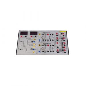
ZE3199 Power Supply Trainer Kit Educational Equipment
ZE3199 Power Supply Trainer Kit for college,university,technical institution,vocational training schools.
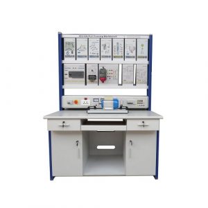
ZE3108F PLC Trainer With Motor Teaching Equipment
ZE3108F PLC Trainer With Motor Teaching Equipment for university,college,technical institution,vocational training schools.
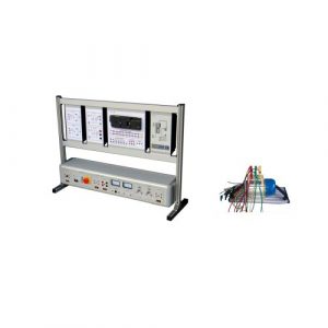
ZE1121 Air Conditioning Electrical Control Board Trainer
ZE1121 Air Conditioning Electrical Control Board Trainer. Jinan Should Shine Didactic Equipment Co., Ltd. is company specialized in manufacture and trading Engineering Educational Equipment,Technical Teaching Equipment, Vocational Training Equipment, Didactic Equipment for university,college, technical institution, polytechnics.Should Shine products has been exported to America,Asia,Europe, Africa, Australia.
ZE1106 Electronics Workbench Technical Educational Equipment
ZE1106 Electronics Workbench Technical Educational Equipment. Jinan Should Shine Didactic Equipment Co., Ltd. is company specialized in manufacture and trading Engineering Educational Equipment,Technical Teaching Equipment, Vocational Training Equipment, Didactic Equipment for university,college, technical institution, polytechnics.Should Shine products has been exported to America,Asia,Europe, Africa, Australia.
Primary Electrician Training Device Educational Equipment
Electrical Training Equipment for university, college, technical institution, vocational training schools.
ZE1107 Electronics Workbench Educational Stand
ZE1107 Electronics Workbench Educational Stand. Jinan Should Shine Didactic Equipment Co., Ltd. is company specialized in manufacture and trading Engineering Educational Equipment,Technical Teaching Equipment, Vocational Training Equipment, Didactic Equipment for university,college, technical institution, polytechnics.Should Shine products has been exported to America,Asia,Europe, Africa, Australia.
ZE1108 Technical Teaching Equipment Electronics Workbench
ZE1108 Technical Teaching Equipment Electronics Workbench. Jinan Should Shine Didactic Equipment Co., Ltd. is company specialized in manufacture and trading Engineering Educational Equipment,Technical Teaching Equipment, Vocational Training Equipment, Didactic Equipment for university,college, technical institution, polytechnics.Should Shine products has been exported to America,Asia,Europe, Africa, Australia.
ZE1105 Electronics Workbench Educational Training Equipment
ZE1105 Electronics Workbench Educational Training Equipment
Jinan Should Shine Didactic Equipment Co., Ltd. is company specialized in manufacture and trading Engineering Educational Equipment,Technical Teaching Equipment, Vocational Training Equipment, Didactic Equipment for university,college, technical institution, polytechnics.Should Shine products has been exported to America,Asia,Europe, Africa, Australia.
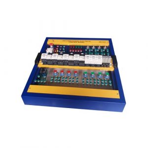
SR2112S Power Electronics Trainer Didactic Equipment
Power Electronics Trainer Didactic Equipment for college,university,technical institute,vocational schools.
ZE3108 PLC Training Simulator Teaching Equipment
PLC training equipment, teaching equipment for college,technical schools,university.
-300x300.jpg)