


- Description
- Inquiry
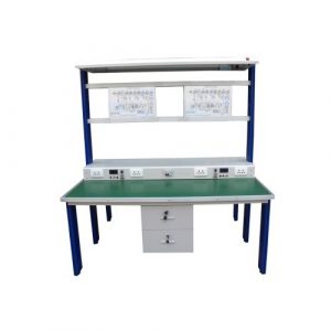
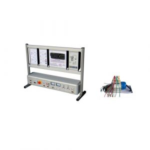
TB-240813-V-203 Motor Control Trainer
Electro Mechanic Component Board
The board enabies the students to perfom experiments with components nomally used inindustrial electrical environments. The components on the front panel can be wired togetherthrough 2 mm terminals for what concems the low voltage controls, and through 4 mm safetyterminals for the connections to the mains or for further applications. All the componentsare identifed through clear synoptic diagrams showing their types and symbols. On the realside of the board, there are switches to allow for the introduction of faults by the teacher.
Components
1 power supply, 24 VAC
1 bipolar switch,1 -0-2
1thermal relay with auxiliary contacts
2timers
5 push-buttons
5 signaling lamps
5 contactors with 5 auxiliary contacts each。
Power supply: single-phase from mains.
Experiments
Single-pole control auxiliaries
Contactor
Logic operators。
Contactor self-supply。
interlock between contactors
Sequentially controlled contactors
Exclusive-OR operator
Static timer
Pulse generator
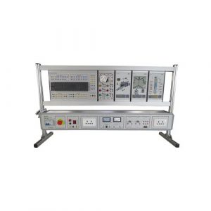
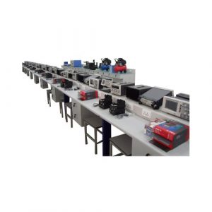
Dissectible Electrical Machines
The system is a complete set of components and modules suitable for assembling therotating electric machines, both for direct current and for alternating current. Students canperfomm a critical and well analyzed assembly, in order to understand the productiortechniques before performing practical tests of the operating characteristics. The system issupplied at low voltages in order to prevent the risk of accidents.
Components and Moduies
power supply module
measurement module
loads and rheostat module
adapter bracket
locking and rotating device
parallel board
pole changing module
electromagnetic brake
star/delta starter
starting and synchronization
base plate
supports with bearing
coupling joints
flexible coupling
electronic speed transducer
assembling screws
wrenchesDC stator
AC stator
rotor with commutator
brush holder with 6 brushes。
cage rotor0
ring rotor
Applications:
Assembly, operation and tests on electric machines and, in particular
Study of the magnetic field
Principles of the electromagnetic induction
Separately shunt, series and compound excited dc motors
Separately shunt, series and compound excited dc generator
Induction motors:three-phase slip ring and squirrel cage, single-phaserepulsion and with capacitor
Dahlander connection。
Synchronous three-phase motor, induction regulator and phase shifter alternator,universal motor
General Parameter
Output (AC): 24 V/14 A, 42V/10A, 3 phase。
Output (DC): 32 V114 A,42 V110 A,0-40 V15 A, 0-8 V/12 A, 3 phase
Speed measurement range: 0- 4000 rpm at 50Hz; 0-6000 rpm at 60Hz
Communication: Modbus RTU RS4850
Encoder resolution: 5 pulses /revolution
C.Electric Machines Lab Simulator
The software can improve students’ didactic experience in electric machines
Required Topics/Lessons
Analysis of magnetic fields and fluxes
Advanced experiments on characterization of machines
Efficiency analysis
Mechanical assembly
Wiring, tests and measurements
Features
Effective guide for student
Possibility to access leaming topics, with theory, instructions and experimentproposals.
Related Products
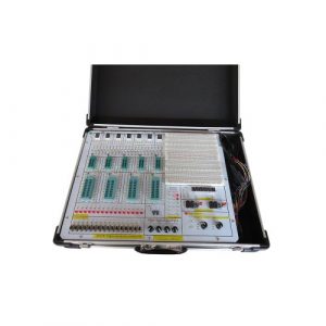
ZE3161 Digital Educational Kit Vocational Training Equipment
ZE3161 Digital Educational Kit Vocational Training Equipment for university,college,technical schools,technical institute, vocational training schools.
ZE1110 Teaching Equipment Digital Electronics Trainer
ZE1110 Teaching Equipment Digital Electronics Trainer
Jinan Should Shine Didactic Equipment Co., Ltd. is company specialized in manufacture and trading Engineering Educational Equipment,Technical Teaching Equipment, Vocational Training Equipment, Didactic Equipment for university,college, technical institution, polytechnics.Should Shine products has been exported to America,Asia,Europe, Africa, Australia.
Primary Electrician Training Device Educational Equipment
Electrical Training Equipment for university, college, technical institution, vocational training schools.
ZE1106 Electronics Workbench Technical Educational Equipment
ZE1106 Electronics Workbench Technical Educational Equipment. Jinan Should Shine Didactic Equipment Co., Ltd. is company specialized in manufacture and trading Engineering Educational Equipment,Technical Teaching Equipment, Vocational Training Equipment, Didactic Equipment for university,college, technical institution, polytechnics.Should Shine products has been exported to America,Asia,Europe, Africa, Australia.
ZE3198 PLC Training Simulator Educational Equipment
ZE3198 PLC Training Simulator Educational Equipment for college,university, technical institute,vocational training schools.
ZE1101 Electronics Workbench Technical Teaching Equipment
ZE1101 Electronics Workbench Technical Teaching Equipment. Jinan Should Shine Didactic Equipment Co., Ltd. is company specialized in manufacture and trading Engineering Educational Equipment,Technical Teaching Equipment, Vocational Training Equipment, Didactic Equipment for university,college, technical institution, polytechnics.Should Shine products has been exported to America,Asia,Europe, Africa, Australia.
ZE1112 Vocational Training Equipment
ZE1112 Vocational Training Equipment. Jinan Should Shine Didactic Equipment Co., Ltd. is company specialized in manufacture and trading Engineering Educational Equipment,Technical Teaching Equipment, Vocational Training Equipment, Didactic Equipment for university,college, technical institution, polytechnics.Should Shine products has been exported to America,Asia,Europe, Africa, Australia.
ZE3108F PLC Trainer With Motor Teaching Equipment
ZE3108F PLC Trainer With Motor Teaching Equipment for university,college,technical institution,vocational training schools.
ZE1107 Electronics Workbench Educational Stand
ZE1107 Electronics Workbench Educational Stand. Jinan Should Shine Didactic Equipment Co., Ltd. is company specialized in manufacture and trading Engineering Educational Equipment,Technical Teaching Equipment, Vocational Training Equipment, Didactic Equipment for university,college, technical institution, polytechnics.Should Shine products has been exported to America,Asia,Europe, Africa, Australia.
ZE1108 Technical Teaching Equipment Electronics Workbench
ZE1108 Technical Teaching Equipment Electronics Workbench. Jinan Should Shine Didactic Equipment Co., Ltd. is company specialized in manufacture and trading Engineering Educational Equipment,Technical Teaching Equipment, Vocational Training Equipment, Didactic Equipment for university,college, technical institution, polytechnics.Should Shine products has been exported to America,Asia,Europe, Africa, Australia.
-300x300.jpg)
-300x300.jpg)