


TB-230426-V-101 Synchro Trainer Vocational Education Equipment for School Lab Electrical Engineering Training Equipment
TB-230426-V-101 Synchro Trainer Vocational Education Equipment for School Lab Electrical Engineering Training Equipment for University, vocational training centers, college, polytechnic
- Description
- Inquiry
TB-230426-V-101 Synchro Trainer Vocational Education Equipment for School Lab Electrical Engineering Training Equipment
1. Equipment introduction
1.1 Overview
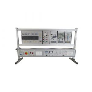
The synchronous trainer is mainly composed of a power module, an auto-angle machine module (auto-angle transmitter + auto-angle receiver + auto-angle transformer), a voltage module and a current module.
The self-aligning machine module (self-aligning transmitter + self-aligning receiver + self-aligning transformer) is a multifunctional independent demonstration system that can be used to study and demonstrate the principles and working principles of AC synchronous transmitters and receivers, and to master Its control principles and control methods cultivate students’ corresponding knowledge and skills.
1.2 Features
(1) Two or both are required to be used at the same time.
(2) When two or two are used at the same time, there is no mechanical connection with each other, only electrical connection.
(3) The non-contact self-aligning machine is safe and reliable in operation, has a long life, and is more reliable in environments lacking maintenance and in any system subject to bumps and vibrations.
(4) The training platform is made of aluminum industrial column profiles to ensure the stability of the training platform; the bottom universal wheels are equipped with brakes and can be flexibly moved and positioned. The training platform is safe to operate (multiple personal and equipment safety protections), standardized, flexible, solid, durable, beautiful and modern.
(5) The experimental circuits and devices are fully configured and can be used in combination to complete practical training content for a variety of subjects.
(6) The training platform has a good safety protection system.
2. Technical parameters
Input power: One-way 230V±10%, 50Hz
weight: 78KG
size : 1240x720x1290mm
The altitude does not exceed 1000m
Ambient temperature -40℃~+55℃ (humidity is 60%-70%)
Relative humidity 95%±3% (air temperature is 20±5%)
3. Components list and detailed introduction
3.1 Main part
| No | Name |
| 1 | main frame |
| 2 | console |
| 3 | Experimental module |
| 4 | Universal wheel |
3.2 Experimental module part
| No | Name |
| 1 | breaker |
| 2 | Step-down isolation transformer |
| 3 | Synchronous transmitter (self-aligning machine transmitter) |
| 4 | Transmit signal module |
| 5 | AC digital voltmeter |
| 6 | AC analog ammeter |
| 7 | AC analog voltmeter |
| 8 | Rocker switch SW1 |
| 9 | Rocker switch SW2 |
| 10 | Power rocker switch |
| 11 | Connection terminal |
| 12 | Rotary Switches |
3.3 Equipment configuration list
| No | Name | Qty |
| Component 1 | Training table | 1 |
| Component 2 | Universal wheel | 4 |
| Component 3 | breaker | 1 |
| Component 4 | Step-down isolation transformer | 1 |
| Component 5 | rocker switch | 3 |
| Component 6 | AC analog voltmeter | 1 |
| Component 7 | AC digital voltmeter | 1 |
| Component 8 | AC analog ammeter | 1 |
| Component 9 | Synchronous transmitter module (self-aligning machine transmitter) | 1 |
| Component 10 | Synchronous receiver module (self-aligning machine receiver) | 1 |
| Component 11 | Rotary Switches | 2 |
| Component 12 | Connection terminal | 29 |
3.4 Accessories
| No | Name | Qty |
| 1 | K4 safety connection cable(yellow) | 10 |
| 2 | K4 safety connection cable(red) | 10 |
| 3 | K4 safety connection cable(blue) | 10 |
| 4 | K4 safety connection cable(green) | 10 |
| 5 | K4 safety connection cable(double) | 10 |
| 6 | fuse(2A) | 5 |
| 7 | fuse(5A) | 5 |
4. Experiment list
Experiment 1 Introduction to self-aligning machine
Experiment 2 Analysis of Synchronous Transmission System
Experiment 3 Voltage measurement of synchronous transmitter and synchronous receiver at different time points
Experiment 4 Analysis of the similarities between synchronized transmitters and receivers and phase pairing
Experiment 5 Analysis of the differences between synchronized transmitters and receivers and phase pairing
Experiment 6 Current of different loads in the circuit
Experiment 7 Controlling motor speed and analysis of forward and reverse directions
Experiment 8 Control Principle of Closed-Loop Control System
Related Products
ZE1110 Teaching Equipment Digital Electronics Trainer
ZE1110 Teaching Equipment Digital Electronics Trainer
Jinan Should Shine Didactic Equipment Co., Ltd. is company specialized in manufacture and trading Engineering Educational Equipment,Technical Teaching Equipment, Vocational Training Equipment, Didactic Equipment for university,college, technical institution, polytechnics.Should Shine products has been exported to America,Asia,Europe, Africa, Australia.
ZE1105 Electronics Workbench Educational Training Equipment
ZE1105 Electronics Workbench Educational Training Equipment
Jinan Should Shine Didactic Equipment Co., Ltd. is company specialized in manufacture and trading Engineering Educational Equipment,Technical Teaching Equipment, Vocational Training Equipment, Didactic Equipment for university,college, technical institution, polytechnics.Should Shine products has been exported to America,Asia,Europe, Africa, Australia.
ZE1112 Vocational Training Equipment
ZE1112 Vocational Training Equipment. Jinan Should Shine Didactic Equipment Co., Ltd. is company specialized in manufacture and trading Engineering Educational Equipment,Technical Teaching Equipment, Vocational Training Equipment, Didactic Equipment for university,college, technical institution, polytechnics.Should Shine products has been exported to America,Asia,Europe, Africa, Australia.
Primary Electrician Training Device Educational Equipment
Electrical Training Equipment for university, college, technical institution, vocational training schools.
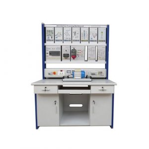
ZE3198 PLC Training Simulator Educational Equipment
ZE3198 PLC Training Simulator Educational Equipment for college,university, technical institute,vocational training schools.
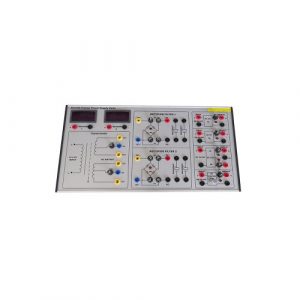
SR2112S Power Electronics Trainer Didactic Equipment
Power Electronics Trainer Didactic Equipment for college,university,technical institute,vocational schools.
ZE2101 Vocational Training Equipment
ZE2101 Vocational Training Equipment. Jinan Should Shine Didactic Equipment Co., Ltd. is company specialized in manufacture and trading Engineering Educational Equipment,Technical Teaching Equipment, Vocational Training Equipment, Didactic Equipment for university,college, technical institution, polytechnics.Should Shine products has been exported to America,Asia,Europe, Africa, Australia.
ZE1101 Electronics Workbench Technical Teaching Equipment
ZE1101 Electronics Workbench Technical Teaching Equipment. Jinan Should Shine Didactic Equipment Co., Ltd. is company specialized in manufacture and trading Engineering Educational Equipment,Technical Teaching Equipment, Vocational Training Equipment, Didactic Equipment for university,college, technical institution, polytechnics.Should Shine products has been exported to America,Asia,Europe, Africa, Australia.
ZE3108 PLC Training Simulator Teaching Equipment
PLC training equipment, teaching equipment for college,technical schools,university.
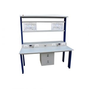
ZE3199 Power Supply Trainer Kit Educational Equipment
ZE3199 Power Supply Trainer Kit for college,university,technical institution,vocational training schools.
-300x300.jpg)
-300x300.jpg)