


- Description
- Inquiry
TB240813S501 SMART Factory Simulator Teaching Equipment Mechatronics Training Equipment
General Description
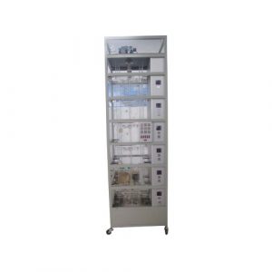
MECHATRONICS LEARNING SYSTEM (4 sets)
This system shall consist of a PLC, I/O connector kit, power supply, master control relay module, portable mounting console, student curriculum, and instructor’s guide for use with a separately specified Mechatronics Workstation. The minimum specifications for each item are below.
The controller shall be an industrial grade type PLC.
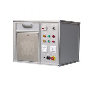
Portable Mounting Console
The portable console shall consist of a sloped, painted, 11-gauge steel panel mounted on a steel base with rubber feet that make it free standing. The PLC, power supply, master control relay and other components shall be mounted to this console and wired together to form a functioning circuit that can be connected to a Mechatronics
workstation or training module. The console shall contain raceways to neatly run all wiring in the system. It shall also be designed so that it can be removed without special tools from the Mechatronics workstation.
I/O Connector Kit
To consist of (3) wiring arms with plug-in DB25 connectors on one end and pre-wired to the PLC i/O on the other end. The cables shall carry a total of at least 24 inputs, 16 outputs.
24VDC Power Supply
This power supply shall be mounted on the training console using a DIN rail and wired to the 1/0 of PLC. It shall be powered by universal AC input, e.g., 220 VAC, 60 Hz, have total current output rating of 5.0 amps. It shall be regulated and have overload protection, an LED power on indicator, and voltage switch. It shall be totally enclosed and include protection for short circuit, overload, over voltage, and over temperature.
Master Control Relay Module
A master control relay shall be mounted to the training console and wired to the PLC so that only the power to the outputs of the PLC are de-energized when the master control relay is de-energized. The reversing motor starter shail use a 3-pole motor contactor with 24VDC coil, manuai override,IEC 60947 rated, and protected terminals.
Terminal connections shall be wired to a DIN rail mounted terminal blocks.
Student Curriculum
The student curriculum supplied shall be designed in a skill-based format that focuses on teaching industry-relevant tasks. This curriculum shall be designed for use in a self-directed student-learning environment, which promotes a sense of rapid accomplishment and student motivation. The objectives shall be accomplished by organizing the learning material into a series of learing activity packets, which are further subdivided into three or more segments per packet. All learning materials needed shall be contained in the packets including text material,laboratory equipment activities, and multimedia directions. No external text sources shall be required. The specific cognitive skills taught by each text passage shall be identified next to the passage. Each lab activity shall be identified by the industrial task taught. All activities shall be highly detailed with step-by-step instructions to facilitate a self-directed learning environment. A combination of step-by-step enabling activities and creative, problem-
solving activities shall be provided. A self-review of five to ten questions shall be provided after each segment.
The student curriculum shall consist of one (1) set of 12 Learning Activity Packets teaching industrial skills in mechatronics. The curriculum shall teach: machine setup, machine adjustment, machine operation, sequence programming, interfacing to IO devices, and program design and documentation of a wide variety of mechatronic applications including; MaterialInventory Feed, Gauging and Testing. Orientation and Processing, Buffering and Sorting. Robotic Assembly, Assembly Torquing, and Programmable Storage.The curriculum shall also cover the operation, adjustment and control of a wide variety of industrial automation components including; pneumatic and electrical lockout/ tagout, master control relay operation, 8 types of electronic sensors, ultrasonic gauging, reversing motor starters, stepper motors, DC PWM motor control, precision bali screw axis drives, clutches, pneumatic screw feed systems, synchronous belt drives, electric motor slides, pneumatic rodless cylinders, rotary actuators, pneumatic brakes, and electrical overloads. The curriculum must be capable of
completely self-diirected and instructor directed study. All subject content as well as hands-on activities shall be included in the student curriculum. All activities must correlate directly to the hardware supplied, with detailed illustrations and diagrams.
Teacher’s Assessment/ Portfolio Guide
The teacher’s package shall contain student data sheets, data sheet solutions, self-review answers, quizzes, quiz answers, student skill record sheets, and assessment directions. A quiz shall be provided for each packet. A question shall be provided in each quiz for each cognitive objective taught and correlated as such. All tasks listed in
the packet shail be listed on personalized student record sheets. The instructor’s Package shall include methods for both cognitive objective assessment and authentic skill assessment, with all skill assessment criteria explained in detail. Detailed instructions and any supplemental material shail be provided for the teacher to perform live assessment of each student.
Hand Tool Package (1 set)
Include the following:
- 3-Drawer Tool Box
Digital Multimeter
Diai Caliper-6-in.
- Hex Wrench Set-13 pieces
Metric Allen Wrench Set-11 pieces
Ultrasonic Meter Wrench
Adjustable Wrench-8-in.(2)
Ignition Wrench Set -20 pieces
Metric Ignition Wrench Set
Screwdriver Set – Straight and Phillips
Flat Blade Screwdriver
Combination Square-6-in.
Tap Handle and Tap
Die Handle and Die
PLC Programming Software (4 sets)
This product includes Programming Software for programmable controllers.
The software shall use ladder logic programming and have all standard programming functions.
It shall provide both online and offline programming, upload and download of programs, and hardcopy documentation. The software shall be supported with an operation and programming manual.
Pick and Place Feeding Station (1 set)
This station shall include
(1) Mobile Workstation,
(1) Operator Station,
(1) Powered Feed Module,
(1) Pick and Place Robot,
(1)Finished Parts Storage Module,
(1) Parts Set,
(1) Pneumatic Distribution Module,
(1) Electrical Distribution Module,
(1) Digital I/O Interface Module, and
(1)Electro-Pneumatic Valve Manifold.
These components shall be assembled, wired and tested to perform material feed sequences when interfaced to a separately-specified programmable controller. The components shall meet the below minimum specifications.
Mobile Warkstation
This workstation shall be constructed of heavy-duty 18-gauge steel, braced, welded, and powder coat painted. It shall be enclosed on the sides and bottom, contain two shelves that extend the length of the workstation and feature two 2-inch rubber grommet hoies on each side. The minimum dimensions shall be 32-in (81 cm) Lx 53.25-in(135
- cm) Hx 14.5-in (37 cm) W. The overall length with the operator station attached shall be 30-in (76 cm). The top work surface shall be 1-inch (2.5 cm) extruded aluminum with slots for mounting. Also supplied shall be four casters, two of which shall be lacking.
and a quick release station connector set. This connector set shall consist of two connectors that join workstations to each other via a quick release method that requires no tools. All components shall be mounted to the workstation in a manner that permits students to easily reposition or replace them.
Operator Station
This station shall be constructed of heavy-duty 14-gauge steel, silkscreened and painted. The minimum dimensions shall be 4-in (10.0 cm) W x 4.63-in (11.8 cm) Hx13.25-in (33.7 cm) L. It shall be totally enclosed and mounted to the mobile workstation.
The operator station shall contain manual electrical pilot devices with industrial quality contacts. These pilot devices shall be mounted to an angled console that is part of the operator station. All devices shall be wired to a compact 14-point digital IO interface module located on top of the operator station enclosure to allow students to take signal
measurements. The following pilot devices shall be included: green, flush push button with N.O. contacts and indicator lamp; red, extended push button with N.C. contacts;
3-position selector switch, one position maintained and two sets of N.O.contacts;
yellow, flush push button with N.O. contacts and indicator lamp; and emergency stop pushbutton with red mushroom operator, illuminated, maintained actuation, and N.C. contacts. The emergency stop pushbutton shall be hardwired to an electrical circuit that connects via the operator station’s digital t0 interface module to the workstation’s PLC master control relay. A 3-inch yellow decal shall surround the e-stop pushbutton. The operator station shall contain relay circuitry that causes the emergency stop pushbutton, when pressed, to also engage the emergency stop function on other linked workstations. The operator station shall tink to other workstations upstream and
downstream via two DB9 connector ports. Each port shall include at least 2 inputs and 2 outputs for control handshaking and additional l0 for emergency stop functions. The operator station shall also include a main power switch with electrical lockout/ tagout with hasp, lock, and tagout. The main power switch shali include a hydraulic/magnetic
circuit breaker with trip free function and 15 Amp rating. The operator station shall also include an inter-station communications link cable with female DB9 connectors on each end.
Electrical Power Module
This module shall consist of a 14-gauge steel enclosure mounted flush to the rear section of the workstation, power distribution cable, and (1) power suppiy cable. The module shall include two electrical power outlets that are interconnected to each other and the power distribution cable. The power distribution cable shall be wired to the main power switch on the operator station. The power supply cable shal be 6-ft (1.82 m) grounded power cord.
Pneumatic Distribution Module
This module shall provide connections for the compressed air supply to various control devices on the workstation. It shall consist of a relieving type pressure regulator; filter, pressure gauge; pneumatic, relieving lockout/ tagout valve with hasp, tagout, and lock;
power air distribution unit with Tee fitting connected to female quick-connect fitting, 3 ft (0.91 m) of rubber air hose with male quick connect fitting, and rubber air hose plumbed to pneumatic lockout/ tagout. The air preparation unit and lockouttagout shall be mounted on top of the workstation at the front, and the power air distribution unit shall
be mounted flush with the rear of the workstation.
Digital I/O Interface Module
This module shall be DIN rail mounted on the workstation. It shall have 72 input/output control terminals and 72 separate terminal sets for power to 10. All control and power terminals shall be interally connected to one of three DB25 connectors and connected to all 10 devices on the workstation. The three DB connectors shall connect to plug-in
cables.
Electro-Pneumatic Valve Manifold
The valve manifold shall include a 4-station manifold with (1) single-solenoid 24 VDC, 2-position, directional control valve and (3) double-solenoid, 24 VDC,2-position, detent directional control valves. The manifold shall be connected via push-lock connectors and flexible, poiyurethane tubing to all pneumatic devices and the main air preparation unit. The manifold shall be mounted to the top of the workstation and wired to the 72- point digital 1O interface module. All valves shall have manual overrides.
Powered Feed Module
This module shall provide a powered material feed sequence that feeds components from an inventory storage unit to the manufacturing process. It shall consist of (1) double-acting pneumatic cylinder, (2) flow contral valves, (1) 8-component gravity-fed storage unit, (2) cylinder-mounted Hall-effect sensors, and (1) photo-electric sensor
with PNP output, diffused mode, and adjustable position. The unit will consist of aluminum structural components that can be adjusted.
Pick and Place Robot
This pick and place robot shall consist of 2-axis electro-pneumatic manipulator plus gripper. The motion shall be Cartesian. The X axis shall use a rodless cylinder with dual rail linear bearing module, adjustable stroke, 10-inch (25.4 cm) travel, (2) magnetic
sensors, (2) flow control valves, and adjustable shock absorber. The Z axis shall use a double-acting cylinder with dual rail linear bearing module, adjustable stroke, 4-inch (10.2 cm) travel, (2) magnetic sensors, and (2) flow control valves. The gripper shall be
a vacuum type with vacuum cup, vacuum generator, vacuum switch, pressure regulator, and pressure gauge. The robot shall be supported by an extruded aluminum structure that provides adjustment of the manipulator horizontally and vertically.
Finished Parts Storage Module
This module shall consist of a molded plastic storage container that mount to an extruded aluminum arm. The container shall be able to hold at least 10 completed components. The container shall be removable without use of tools when the station is used in a multi-station application.
Parts Set
The parts set shall consist of directional control valve parts. When combined with parts from other stations, the parts shall be capable of being assembled by an automatic process and result in a working, industrial-quality pneumatic directional control valve that is rated for at least 100 psi/ 690kPa. The parts set shall include: (8) acrylic valve bodies.
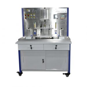
Gauging Station (1set)
This station shall include
(1) Mobile Workstation
(1) Operator Station,
(1) Traverse Shuttle,
(1) Ultrasonic Measurement Module,
(1) Proximity Gauging Module,
(1)Part Transfer Module,
(1) Part Reject Module,
(1) Finished Parts Storage Module,
(1) Pneumatic Distribution Module,
(1)Electrical Distribution Module,
(1) DigitalI/O Interface Module and
(1) Electro-Pneumatic Valve Manifold.
These components shal be assembled, wired and tested to perform a material thickness inspection, part feature presence inspection, and material transfer sequence when interfaced to a separately-specified programmable controller. The components shall meet the below minimum specifications:
Mobile Workstation
This workstation shall be constructed of heavy-duty 18-gauge steel, braced, welded, and powder coat painted. It shall be enclosed on the sides and bottom, contain two shelves that extend the length of the workstation and feature two 2-inch rubber grommet holes on each side. The minimum dimensions shall be 32-in (81 cm) L x 53.25-in(135
- cm) H x 14.5-in (37 cm) W.The overali length with the operator station attached shall be 30-in (76 cm). The top work surface shall be 1-inch (2.5 cm) extruded aluminum with slots for mounting. Also supplied shall be four casters, two of which shail be locking, and a quick release station connector set. This connector set shal! consist of two connectors that join workstations to each other via a quick release method that requires no tools. All components shall be mounted to the workstation in a manner that permits students to easily reposition or replace them.
Operator Station
This station shait be constructed of heavy-duty 14-gauge steel, silkscreened and painted. The minimum dimensions shall be 4-in (10.0 cm) W x4.63-in (11.8 cm) H x 13.25-in (33.7 cm) L.It shall be totally enclosed and mounted to the mobile workstation.
The operator station shall contain manual electrical pilot devices with industry quality contacts. These pilot devices shall be mounted to an angied console that is part of the operator station. All devices shail be wired to a compact 14-point digital I0 interface module located on top of the operator station enclosure to allow students to take signal
measurements. The following pilot devices shall be included: green, flush push button with N.O. contacts and indicator lamp; red, extended push button with N.C.contacts;
3-position selector switch, one position maintained and two sets of N.O.contacts;
yellow, flush push button with N.O. contacts and indicator lamp; and emergency stop pushbutton with red mushroom operator, illuminated, maintained actuation, and N.C. contacts. The emergency stop pushbutton shall be hardwired to an electrical circuit that
connects via the operator station’s digital 10 interface module to the workstation’s PLC master control relay. A 3-inch yellow decal shall surround the e-stop pushbutton. The operator station shall contain relay circuitry that causes the emergency stop pushbutton, when pressed, to also engage the emergency stop function on other linked
workstations. The operator station shall link to other workstations upstream and downstream via two DB9 connector ports. Each port shall include at least 2 inputs and 2 outputs for control handshaking and additional 10 for emergency stop functions. The operator station shail also include a main power switch with electrical lockout/ tagout with hasp, lock, and tagout. The main power switch shall include a hydraulic/magnetic circuit breaker with trip free function and 15 Amp rating. The operator station shall also include an inter-station communications link cable with female DB9 connectors on each end.
Electrical Power Module
This module shall consist of a 14-gauge steel enclosure mounted flush to the rear section of the workstation, power distribution cable, and power supply cable. The module shall include two electrical power outlets that are interconnected to each other and the power distribution cable. The power distribution cable shall be wired to the main power switch on the operator station. The power supply cable shall be 6-ft (1.82 m) grounded power cord.
Pneumatic Distribution Module
This module shail provide connections for the compressed air supply to various control devices on the workstation. It shall consist of a relieving type pressure regulator, filter, pressure gauge; pneumatic, relieving lockout/ tagout valve with hasp, tagout, and lock;
power air distribution unit with Tee fitting connected to female quick-connect fitting,3 ft (0.91 m) of rubber air hose with male quick connect fitting, and rubber air hose plumbed to pneumatic lockout/ tagout. The air preparation unit and lockout/tagout shall be mounted on top of the workstation at the front, and the power air distribution unit shall be mounted flush with the rear of the workstation.
Digita/ I/O interface Module
This module shall be DIN rail mounted on the workstation. It shall have 72 input/output control terminals and 72 separate terminal sets for power to 10. All control and power terminals shall be internally connected to one of three DB25 connectors and connected
to all 10 devices on the workstation. The three DB connectors shall connect to plug-in cables.
Electro-Pneumatic Valve Manifoid
The valve manifold shall include a 3-station manifold with (2) single-soienoid 24 VDC, 2-position,directional control valves and double-solenoid, 24 VDC, 2-position, detent directional control valve. The manifold shall be connected via push-lock connectors and flexible, polyurethane tubing to all pneumatic devices and the main air preparation unit.
The manifoid shall be mounted to the top of the workstation and wired to the digital lO interface module. All valves shal! have manual overrides.
Traverse Shuttle
The traverse shuttle shall provide linear transport of parts across the width of the workstation. It shall be a D.C. electric motor with precision gearbox reduction unit, powered using a reversing motor starter control. The reversing motor starter shall use
(2) 3-pole motor contactors with 24 VDC coils, manual overrides, mechanical interlock, IEC 60947rated, and protected terminals. The traverse shall consist of two linear guide rods and two precision linear bearings that guide the carriage. The maximum travel shall be 11 inches (27.9 cm) with adjustable stops. Two adjustable position, over-travel limit switches shall be provided. The motor shall drive a precision ball screw through a paraliel shaft arrangement that uses a synchronous beit and overrunning clutch.
Industrial quality ball bearing modules shall precisely position the bail screw. The carriage shall be designed with fixtures to locate and transport components for the manufacturing process. A single-acting, non-rotating component lift cylinder shall be mounted to the axis. This cylinder shall use a quick exhaust valve.
Ultrasonic Measurement Module
This module shall consist of an ultrasonic sensor that provides a measurement of part thickness. It shall have an adjustable threshold window mode, 50-500 mm sensing range, with 24 VDC output, 3 LED’s (for power, status, and error), 0.007-inch accuracy, 50 m.s. response, and 0.020-inch hysteresis. It shall also have a programming input
and sync input. An inductive sensor shall trigger the uitrasonic read action. The inductive sensor shail have PNP output and adjustments for horizontal and vertical position.
Proximity Gauging Module
This module shall consist of a photo-electric sensor that performs a port presence inspection process. The sensor shall have PNP output, diffused mode operation with background suppression, visible red LED light source,3 mm spot, 25 mm sensing distance, and adjustabie vertical and horizontal position.
Powered Parts Transfer Module
This module shall provide a powered material transfer sequence that feeds components to either the finished parts storage module or another workstation. It shall consist of a double-acting pneumatic cylinder, (2) flow control valves, 10-component, molded, plastic storage container, and (2) cylinder-mounted magnetic sensors.
Powered Parts Reject Module
This module shall provide a powered material reject sequence that feeds components to a rejected parts storage container. It shall consist of a double-acting pneumatic cylinder, (2) flow control valves, 10-component, molded, plastic storage container, and (2) cylinder-mounted magnetic sensors. The reject container shall be mounted to an extruded aluminum arm.
Finished Parts Storage Module
This module shall consist of a molded plastic storage container that mounts to an extruded aluminum arm. The container shall be able to hold at least 10 completed components. The container shall be removable without use of tools when the station is used in a multi-station application.
Parts Set
The parts set shall consist of (4) acrylic reject directional control valve bodies.
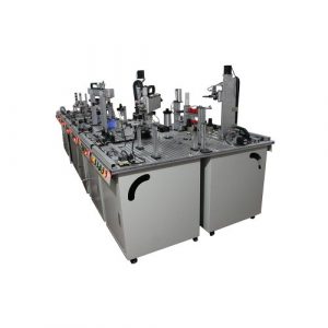
Orientation-Processing Station (1 set)
This station shall include
(1) Mobile Workstation,
(1)Operator Station,
(1) 8-Station Rotary Index Table,
(1) Pick and Place Pneumatic Robot,
(1) Fiber Optic Gauging Module,
(1) Part Transfer Module,
(1) Finished Part Storage Module,
(1) Pneumatic Distribution Module;
(1) Electrical Distribution Module,
(1) DigitalI/O Interface Module and
(1) Electro-Pneumatic Valve Manifoid.
These components shall be assembled, wired and tested to perform part orientation inspection, reorientation, and material processing (with separately-specified optional drill module) when interfaced to a separately-specified programmable controller. The components shal meet the below minimum specifications.
Mobile Workstation
This workstation shall be constructed of heavy-duty 18-gauge steel, braced, welded.
and powder coat painted. It shall be enclosed on the sides and bottom, contain two shelves that extend the length of the workstation and feature two 2-inch rubber grommet holes on each side. The minimum dimensions shali be 32-in(81 cm) L x 53.25-in(135cm) Hx14.5-in(37 cm) W. The overall length with the operator station attached shail
be 30-in (76 cm). The top work surface shall be 1-inch (2.5 cm) extruded aluminum with slots for mounting. Also supplied shall be four casters, two of which shall be locking.
and a quick release station connector set. This connector set shali consist of two connectors that join workstations to each other via a quick release method that requires no tools. Ail components shall be mounted to the workstation in a manner that permits students to easily reposition or replace them.
Operator Station
This station shall be constructed of heavy-duty 14-gauge steel, silkscreened and painted. The minimum dimensions shall be 4-in (10.0 cm)W x4.63-in(11.8 cm)Hx 13.25-in(33.7 cm) L. It shall be totally enclosed and mounted to the mobile workstation.
The operator station shail contain manua| electrical pilot devices with industry quality contacts. These pilot devices shall be mounted to an angled console that is part of the operator station. All devices shall be wired to a compact 14-point digital1O interface module located on top of the operator station enclosure to allow students to take signal
measurements. The following pilot devices shall be included: green, flush push button with N.O.contacts and indicator lamp; red, extended push button with N.C. contacts;
3-position selector switch, one position maintained and two sets of N.O.contacts;
yellow, flush push button with N.O. contacts and indicator lamp; and emergency stop pushbutton with red mushroom operator, illuminated, maintained actuation, and N.C.
contacts. The emergency stop pushbutton shall be hardwired to an electrical circuit that connects via the operator station’s digital 10 interface module to the workstation’s PLC master control relay. A 3-inch yellow decal shall surround the e-stop pushbutton. The operator station shall contain relay circuitry that causes the emergency stop
pushbutton, when pressed, to also engage the emergency stop function on other linked workstations. The operator station shall link to other workstations upstream and downstream via two DB9 connector ports. Each port shall include at least 2 inputs and 2 outputs for control handshaking and additional lO for emergency stop functions. The
operator station shall also include a main power switch with electrical lockout/ tagout with hasp, lock, and tagout. The main power switch shall include a hydraulic/magnetic circuit breaker with trip free function and 15 Amp rating. The operator station shall also include an inter-station communications link cable with female DB9 connectors on each end.
Electrical Power Module
This module shall consist of a 14-gauge steel enclosure mounted flush to the rear section of the workstation, power distribution cabie, and power supply cable. The module shali include two electrical power outlets that are interconnected to each other and the power distribution cable. The power distribution cabie shall be wired to the main power switch on the operator station. The power supply cable shall be 6-ft (1.82 m) grounded power cord.
Pneumatic Distribution Module
This module shail provide connections for the compressed air supply to various control devices on the workstation. It shail consist of a relieving type pressure regulator; filter;
pressure gauge; pneumatic, relieving lockout/ tagout valve with hasp, tagout, and lock;
power air distribution unit with Tee fitting connected to female quick-connect fitting, 3 f (0.91 m) of rubber air hose with male quick connect fitting, and rubber air hose plumbed to pneumatic lockout/ tagout. The air preparation unit and lockout/tagout shall be mounted on top of the workstation at the front, and the power air distribution unit shall
be mounted flush with the rear of the workstation.
Digital I/O Interface Module
This module shall be DIN rail mounted on the workstation. It shall have 72 input/output control terminals and 72 separate terminal sets for power to 10. All control and power terminals shall be internally connected to one of three DB25 connectors and connected
to all 10 devices on the workstation. The three DB connectors shall connect to plug-in cables.
Electro-Pneumatic Vaive Manifold
The valve manifold shall include a 4-station manifold with single-solenoid 24 VDC, 2- position, directional control vaive and (3) double-solenoid,24VDC,2-position, detent directional control vaives. The manifold shall be connected via push-lock connectors and flexible, polyurethane tubing to all pneumatic devices and the main air preparation unit. The manifold shall be mounted to the top of the workstation and wired to the digital IO interface module. Ail valves shall have manual overrides.
Rotary Index Table
The rotary index table shall provide positioning of parts at 8 software-programmable positions located 45 degrees apart from each other around the table. The table disk shall consist of painted 11-gauge steel on top of 16-gauge brushed stainless steel and have a minimum diameter of 15 inches (38.1 cm). The table shall be designed with
fixtures to locate and transport parts for the manufacturing process. It shall be operated by a motion control system that uses a precision stepper-motor. The stepper motor shall have a resolution of 51,200 steps per revolution and operate in the 12-48 VDC range.
The motion control system shall be integrated with the motor. It shall be PC software programmable via RS-485 communications and include the following programming functions: home, limit plus, limit minus, go, stop, pause, jog plus, jog minus, analog in, moving, fault, stall, velocity change, trip on input, trip on position, basic math functions, logical math expressions, and branch and call subroutines. The motion control system shall include (4) 24 VDC discrete I/O, and analog input (0-5VDC or 4-20 ma). The system shall include Windows-compatible programming software and RS-485 to RS-
232communications cable with serial port. The motion control system shall be connected to the rotary table via a zero-backlash, flexible coupling, precision worm gear right-angle drive, and ball bearing guides. A homing sensor shall be mounted to the table structure. This sensor shall be an inductive type with (2) PNP outputs, cylindrical body, indicator light, and shall be position adjustable. A part present sensor shall be installed at position 1. This sensor shall be a capacitiye type with cylindrical body, PNP output, indicator light, adjustable sensitivity, and adjustable horizontal and vertical position. A part present sensor shall also be installed at position 3. This sensor shall be a capacitive type with cylindrical body, PNP output, indicator light, adjustable sensitivity, and adjustable horizontal and vertical position.
Pick and Place Pneumatic Robot
This pick and place robot shall consist of a 2-axis electro-pneumatic manipulator plus gripper. The motion shall be Cartesian. The Z axis shall use a twin bore double-acting pneumatic cylinder module with adjustable stroke,0.75-inch(1.9 cm) travel, (2) magnetic sensors, and (2) flow control valves. The rotary axis shall use a rack and pinion pneumatic actuator with adjustable stroke,180-degree rotation with 45-degree adjustment on each end, (2) magnetic sensors, and (2) flow control valves. The gripper shall be a 2-point curvilinear type with double acting actuator, and (2) flow control valves.
Parts Transfer Module
This module shall provide a powered material transfer sequence that feeds components to either the finished parts storage module or another workstation. It shall consist of double-acting pneumatic cylinder, (2) flow control valves and (2) cylinder-mounted magnetic sensors.
Finished Parts Storage Module
This module shall consist of a molded plastic storage container that mount to an extruded aluminum arm. The container shall be able to hold at least 10 compieted components. The container shali be removable without use of tools when the station is used in a multi-station application.
Servo Robot Assembly Station (1 set)
This station shall include:
(1)Mobile Workstation,
(1) Operator Station,
(1) Spool Insertion Module,
(1) Screw Feed Module,
(1) Spring/ Knob Feed Module,
(1) Screw/ Knob Engagement Module,
(1)Assembly Shuttle Module,
(1) Finished Parts Storage Module,
(1) Parts Presentation Module,
(1) Pneumatic Distribution Module,
(1) Electrical Distribution Module,
(1) Digital I/O Interface Module,and
(1) Electro-Pneumatic Valve Manifold.
These components shall be assembled, wired and tested to perform an assembly sequence when interfaced to a separately-specified programmable controller. The components shall meet the below minimum specifications.
Mobile Workstation
This workstation shall be constructed of heavy-duty 18-gauge steel, braced, welded, and powder coat painted. It shall be enclosed on the sides and bottom, contain two shelves that extend the length of the workstation and feature two 2-inch rubber grommet holes on each side. The minimum dimensions shall be 32″ (81 cm) Lx 53.25″ (135 cm) H x 14.5″ (37 cm) W. The overali length with the operator station attached shall be 30″ (76 cm). The top work surface shail be 1-inch (2.5 cm) extruded aluminum with slots for mounting. Also supplied shall be four casters, two of which shall be locking, and a quick release station connector set. This connector set shall consist of two connectors that join workstations to each other via a quick release method that requires no tools.All components shall be mounted to the workstation in a manner that permits students to easily reposition or replace them.
Operator Station
This station shall be constructed of heavy-duty 14-gauge steel, silkscreened and painted. The minimum dimensions shall be 4″ (10.0 cm) Wx 4.63″ (11.8 cm) H x 13.25″ (33.7 cm) L. It shall be totally enclosed and mounted to the mobile workstation. The operator station shall contain manual electrical pilot devices with industrial quality
contacts. These pilot devices shall be mounted to an angled console that is part of the operator station. All devices shall be wired to a compact 14-point digital 10 interface module located on top of the operator station enclosure to allow students to take signal measurements. The foliowing pilot devices shall be included: green, flush pushbutton with N.O. contacts and indicator lamp; red, extended push button with N.C. contacts;
3-position selector switch, one position maintained and two sets of N.O.contacts;
yellow, flush pushbutton with N.O.contacts and indicator lamp; and emergency stop pushbutton with red mushroom operator, illuminated, maintained actuation, and N.C. contacts. The emergency stop pushbutton shall be hardwired to an electricai circuit that connects via the operator station’s digital 1O interface module to the workstation’s PLC master control relay. A 3-inch yellow decal shall surround the e-stop pushbutton. The operator station shali contain relay circuitry that causes the emergency stop pushbutton, when pressed, to also engage the emergency stop function on other linked workstations. The operator station shall link to other workstations upstream and downstream via two DB9 connector ports. Each port shall include at least 2 inputs and 2 outputs for control handshaking and additional l0 for emergency stop functions. The operator station shall also include a main power switch with electrical lockout/ tagout with hasp, lock, and tagout. The main power switch shall include a hydraulic/magnetic circuit breaker with trip free function and 15 Amp rating. The operator station shall also include an inter-station communications link cable with female DB9 connectors on each end.
Electrical Distribution Module
This module shail consist of a 14-gauge steel enclosure mounted flush to the rear section of the warkstation, power distribution cable, and (1) power supply cable. The module shall include two electrical power outlets that are interconnected to each other and the power distribution cable. The power distribution cable shall be wired to the main power switch on the operator station. The power supply cable shall be 6-ft(1.82 m) grounded power cord.
Pneumatic Distribution Module
This module shall provide connections for the compressed air supply to various control devices on the workstation. It shall consist of a relieving type pressure regulator; filter, pressure gauge; pncumatic, relieving lockout/ tagout valve with hasp, tagout, and lock; power air distribution unit with Tee fitting connected to female quick-connect fitting.3ft (0.91 m) of rubber air hose with male quick connect fitting, and rubber air hose plumbed to pneumatic lockout/ tagout. The air preparation unit and lockout/tagout shail be mounted on top of the workstation at the front, and the power air distribution unit shall
be mounted flush with the rear of the workstation.
Digital I/O Interface Module
This module shall be DIN rail mounted on the workstation. It shall have 72 input/output control terminals and 72 separate terminal sets for power to 10. All control and power terminals shall be internally connected to one of three DB25 connectors and connected
to all t0 devices on the workstation. The three DB connectors shall connect to plug-in cables.
Eloctro-Pneumatic Valve Manifold
The vaive manifold shall include a 6-station manifold with (5) single-solenoid 24 VDC, 2-position, directional control valves and (1) double-solenoid, 24 VDC,2-position, detent directional control valve. The manifold shall be connected via push-lock connectors and flexible, polyurethane tubing to all pneumatic devices and the main air
preparation unit. The manifold shal be mounted to the top of the workstation and wired to the digital 10 interface module. All valves shall have manual overrides
Spool Insertion Module
This module shall provide a powered materlal feed sequence that can feed one of two types of spools from two inventory storage units to the manufacturing process. It shall consist of (1) single-acting pneumatic cylinder, double-acting pneumatic cylinder. (3) flow control valves, (2) 8-component storage units,(4) cylinder-mounted magnetic sensors, and (2) inductive parts-empty sensors with PNP output. The unit will consist of aluminum structural components that can be adjusted.
Screw Feed Module
This module shall provide pneumatic feeding ofscrews to the assembly process. It shall consist of {1) flexible, polyurethane, transparent screw feed tube, 36-inches(91.5cm) long and 0.875-inches(22 mm) diameter, and (1) pressure regulator valve. The module
shall also include a screw escapement mechanism and screw queue mechanism that are pneumatic-powered. These mechanisms shall include: (3) single-acting pneumatic cylinders and (1) inductive sensor. This unit will include aluminumstructural components that can be adjusted.
Spring/ Knob Feed Module
This module shall provide a material feed device that feeds manual button-type operators and springs from an inventory storage unit to the manufacturing process via a servo robot. It shall consist of gravity feeder and fixtures to interact with the robot.
Screw/ Knob Engagement Module
This module shall perform final assembly of screw, operator, spring, spoal and valve body. It shail consist of (1) double-acting pneumatic cylinder, (1) flow control valve, (2) cylinder-mounted magnetic sensors, and a screw engagement motor. This motor shall be a D.C. motor with foot mount, precision gearbox reduction unit, and friction engagement tool. The motor shall be powered using a motor starter control. The motor starter shall use 3-pole motor contactor with 24 VDC coil, manual override,IEC 60947rated, and protected terminals.
Assembly Shuttle Module
This module shall provide a powered material handling sequence that transports part assemblies between two assembly positions. It shall consist of (1) double-acting rodiess pneumatic cylinder, (2) flow control valves, and (2) cylinder-mounted magnetic sensors.
Two powered clamps sha”also be provided. These clamps will include fixtures, (2) singie-acting pneumatic cyunders, (2) flow control valves, and (2) cylinder-mounted magnetic sensors.
Finished Parts Storage Module
This module shall consist of a molded plastic storage container that mounts to an extruded aluminum arm. The container shall be able to hold at least 10 completed components. The container shall be removable without use of tools when the station is used in a muiti-station application.
Parts Presentation Module
This module shall consist of an extruded aluminum structure and fixture for part presentation to the system. The module shall be able to be adjustable vertically and horizontally.
Parts Set
The parts set shall consist of directional control valve parts. When combined with parts from other stations, the parts shall be capable of being assembied by an automatic process and result in a working, industrial-quality pneumatic directional control valve that is rated for at least 100 psi/690kPa.The parts set shall include: (8) 3-way valve
spools, (8) 4-way valve spools, (8) manual operators, (8) bolts and (8) spool return springs.
Smart Robot Workcell (1 set)
Components include:
Robot with Advanced Software and Ethernet IP
Area Laser Scanner
Smart Robot Workstation with discrete1/O, pneumatic, Ethernet I/O Interface
Panel
Robot-to-PLC Interface
Cabling Set
Gripper Fixture Set
- Quick Connect System; SystemConfiguration and Integration Prep
Robot Arm Integration to Mechatronics(1set)
(2) Custom Mounting Brackets with Actuators
(1)Compressed Air Piping
Single-Station Laser Scanner (1 set)
This product provides safety at the front of the Smart Robot Workcell. For Mechatronics systems with multiple Robot Workcells, customers must have (2) Laser Scanners and (1)Communication Kit.
.Laser Scanner System with one laser scanner
Mounting Fixture Set
Cable Set
- Integration Engineering and Programming
Mechatronics HMI Terminal Learning System (1 set)
This system teaches how to use human machine interface (HM!) to control and monitor an automated line.
HMI
- 5.5-in. screen
- 320×240 resolution
HMI Terminal Module
EtherNot Cable
- Cat 5E patch cable, 14′, gray
Workstation Pedestal Mounting Module
- Rigid, adjustable mounting module allows the HMI to be situated in the optimal position
Student Curriculum
This system shall consist of three (3) Learning Activity Packets containing no less than thirteen (13) industry skilis. Topics shall include: HMI construction;HMI configuration; HMI operation; application editing; component identification; The student curriculum
supplied shall be designed in a skill-based format that focuses on teachingindustry relevant tasks. The objectives shall be accomplished by organizing the leaming material into a series of leaming activity packets, which are further subdivided into three or more
segments per packet. All leaming materials needed shall be contained in the packets including text material and laboratory equipment activities. No external text sources shail be required. The specific cognitive skills taught by each text passage shall be identified next to the passage. Each lab activity shall be identified by the industrial task
taught. All activities shall be highly detailed with step-by-step instructions to facilitate a self-directed learning environment. A combination of step-by-step enabling activities and creative, problem-solving activities shall be provided. A self-review of five to ten
questions shail be provided after each segment. The curriculum must be capable of both self-directed and instructor directed study. All activities must correlate directly to the hardware supplied, with detailed illustrations and diagrams.
Teacher’s Assessment Guide
A teacher’s assessment guide shall be provided. It shall contain student data sheets, data sheet solutions, self-review answers, quizzes, quiz answers, student skill record sheets, and authentic assessment. A quiz shall be provided for each packet. A question shall be provided in each quiz for each cognitive objective taught. All tasks listed in the packet shall be listed on personalized student record sheets. The teacher’s assessment guide shall include directions for authentic skill assessment.
Mechatronics Smart Device Learning (1 set)
This learning system shall be designed to teach communications between a stack light and other intelligent automation devices using EtherNetIP in a Smart Factory environment. At minimum, the learning system shail consist of: EtherNet/iP communications I/O module, stack light module, cable set, student curriculum, student
reference guide, and instructor’s guide. The system shall be fully assembled and wired to mount to a mobile workstation or a table top surface.
Smart Factory Ethernet Learning System (1 set)
This learning system shall be designed to teach EtherNet/1Pcommunications between various intelligent automation devices in various topologies in a Smart Factory environment to efficiently control and monitor an automated manufacturing process. At minimum, the learning system shall consist of: (1)managed EtherNet/IP switch module, (1) unmanaged Ethernet switch module, (1) cabie sot, (1) student curriculum, student reference guide, and (1) instructor’s guide. The system shall be fully assembled and wired to mount to mobile workstations or a table top.
Smart Factory Mechatronics Barcode (1 set)
This learning system teaches learners how barcode readers are used within an automated line to identify components, enter serial numbers in a database, and sort items into groups.
Multi-technology Interactive e-Learning solution with the use of different teaching tools such as text, 3D animation, video, audio and virtual simulation (1 year subscription)
Learning Management System {LMS) Inckuded
‘ User-friendly Navigation with Skills on/OffControl
SCORM to Other LMS Systems
Custom LMS Branding Available. Put your school logo or organization’s logo and colors on the LMS home screen.
Pre-/Post-Course Quizzes. Create a valuable metric to track progress.
Easy-to-Use Reporting Tools. Customizable reporting tools will help evaluate progress.
Custom Course Set-Up
Choose from thousands of eLeaming modules to create an almost innumerable combination of courses that can exactly fit your training needs.
Reduce Training Cost with eAssessment
Distance eLeaming eAssessment to quickly reveal strengths and identify weaknesses.
Utiize this program to assess individuals, departments, or the entire organization.
eLearning Categories
- AUTOMATION
- Ethernet for Mechatronics
2.Mechatronics HMI
3.Mechatronics
4.Mechatronics Profibus
5.Mechatronics Troubleshooting
6.Mechatronics Troubleshooting with PLC
7.Mechatronics-PLC
8.Mechatronics-Ethernet/IP
- Panel view Operator interface
10.Mechatronics Simulation (Smart Factory)
11.Mechatronics Simulation
- Pegasus Robotics Simuiation
13.Robotics and Computer Programming
14.Robotics 1
15.MechatronicsCNC Mill
- Machine Vision Inspection Systems
- Machine Vision Inspection Systems
18.Mechatronics Troubleshooting System-PLC
19.MechatronicsRF Identification System
20.Mechatronics Barcode Identification
21.MechatronicsRF Identification System
22.Mechatronics RF Identification System-PLC
- Tabletop Mechatronics
25.Mechatronics HMi
25.Mechatronics Barcode Identification -PLC
- Mechatronics Barcode Identification-Barcode
27.Table-Top Mechatronics Servo Robot System
28.Table Top Smart Factory RFID/Sensors
29.Mechatronics Barcode Product Identification-PLC Controller
- Tabletop Smart Factory Ethernet
31.Tabletop Smart Factory Manufacturing Execution System
- Smart Factory Barcode System
- Mechatronics RFID
34.Smart Factory Vision Inspection System
- Smart Factory Visual Communication System
36.Mechatronics System
37.Mechatronics – Professional
- Smart Factory Sensor System – Pneumatics/Vacuum
- Smart Factory Sensor System -Ultrasonic
- Smart Factory Sensor System -Photoeye
- Smart Factory Device Learning System – Stack Light
- Smart Factory Sensor System- Electrical Current
- Smart Factory Sensor System -Analog Position
- Smart Factory Sensor System -Analog Pressure
45.Tabletop Smart Factory Visual Communications
- Smart Factory Barcode System – Basic
- MechatronicsRFID AB L16
- Smart Factory Ethemet
49.Smart Factory Network Security Leaming System
- Smart Factory Manufacturing Execution System
51.Smart Factory Visual Communications
52.Smart Factory Sensor System- Pneumatics/ Vacuum Advanced
- Smart Factory Sensor System – Ultrasonic Advanced
- Smart Factory Sensor System – Photoeye Advanced
- Smart Factory Device Leamning System Stack Light
56.Smart Factory Sensor System- Electrical Current
57.Smart Factory Sensor System -Analog Position
58.Smart Factory Sensor System-Analog Pressure
59.Mechatronics
60.Computer Control 2
- Principles of Robotics
- Principles of Factory Automation
63.Principles of Robotics
II.ELECTRONICS
1.DC Electronic Drives
- Portable Pic
- Portable Plc Troubleshooting
4.PLC Analog Application
5.PLC ControlNet
6.Mastering Programmable Controllers
7.PLC Statement List
8.PLC Analog
- PLC Profibus
10.MPC
11.PLC Graph Programming-
12.MPC-iBus
13.MPC
14.Mastering Programmable Controllers
15.PLC Troubleshooting
- Programmable Controller
- Mastering Programmable Controllers
- Power and Control Electronics
19.AC Motor Drives
20.AC Motor Drive Troubleshooting
21.Electrical Control Systems
22.Variabie Frequency AC Drive
23.AC Electronic Drives
24.PLC Motor Control
25.PLC Motor Control
26.Portable PLC Learning System
- Portable PLC with Troubleshooting
28.PLC Troubleshooting-PLC
29.PLC Troubleshooting
30.Computer Control 1
III.ELECTRICAL
1.Electric Motor Control
2.AC/DC Electrical Systems
3.Electrical Control 1
- Portable Electric Relay Control Troubleshooting
- Electric Relay Control
6.AC/DC Electrical Systems
- Electric Motor Control
- Electric Motor Control Troubleshooting
- Electrical Fabrication 1
10.Motor Braking
11.Reduced Voltage Starting
12.Electronic Sensors
13.Electronic Counter
14.SCR Speed Control
- Electric Wiring System
16.PLCNFD Wiring System
- Industrial Soldering
- Ethernet and Analog Wiring
- Electrical Power Distribution
- Electric Motor Control
- Motor Troubleshooting System
22.Rotating Electric Machines
23.DC Generators
24.Wound Rotor Motor
25.Rotating Electrical Machines
- GREEN ENERGY
1.Wind Concepts
- Turbine Electric Hub Troubleshooting
- Turbine Generator Control Troubleshooting
- Turbine Nacelle Troubieshooting
5.Solar Concepts
6.Solar Site Anatysis
- Altemative Energy
- Solar Thermal Troubleshooting – Open-Loop
9.Solar Thermal Troubleshooting – Closed-Loop
10.Solar Thermal Instailation
11.Solar PV Troubleshooting
12.Solar Grid-Tie
- Data Acquisition
- Solar Photovoltaic Installation
V.LEAN MANUFACTURING
1.Lean Overview and Workplace Organization
- Introduction to Lean
3.5S
4.Total Productive Maintenance
5.Poka-Yoke
6.Lean Theory
7.Lean Process Flow
- Visual Workplace
- Standardized Work
- Kaizen
11.Value Stream Mapping
12.Set-Up Reduction
13.Six Sigma
- MACHINING
1.Machine Tools 1
2.Machine Tools 2
3.Machine Tools 3
4.Manuai Machine Tools
5.CNC Machine Tools 1
6.CNC Machine Tools 2
7.CNC Machine Toois 3
- Principles of CNC
9.CNC Control
10.Principles of Tuming
11.Principles of Machining Centers
12.Principles of Grinding
13.Principles of Workholding
- Principies of Coolants and Oils
- Principies of Gear Manufacturing
16.Principles of Tooling
17.Tooling for Tuming
18.Tooling for Machining Centers
19.Tooling for Grinding
20.Tooling for Tapping
VII. MANUFACTURING PROCESS
1.Product Finishing
- Production Assembly
- Split Flange Coupling Assembly
- Eiectric Torque Wrench Assembly
5.Print Reading 1
6.Welding Technology 1
- Computer-Aided Design 1
- Computer Aided Design 2
9.Wiring Harness Assembly
- Contamination
- Fasteners
- Gaskets
13.Stall Bar Assembly
- Instrumented DC-Electric Torque Wrench Assembly
15.Computer-Aided Manufacturing 1
- Blueprint Reading
17.AWS Welding Symbols on Blueprints
- General Dimensioning and Tolerances
19.Geometric Dimensioning and Tolerancing
VIII.MATERIALS
- Plastic Mold Design
- Manufacturing Processes 3
- Structural Engineering 1
- Structural Engineering 2
- Surveying
- Materials Engineering 1
- Principles of Materlals -Ferrous Metals
- Principles of Materials -Non-Ferrous Metals
- Principles of Heat Treating
10.Principles of Plastics
11.Principies of Composites
12.Principles of Ceramics
IX.MECHANICAL
1.Vibration Analysis
- Pump Systems
3.Multiple ‘Pump
4.Turbine Pump
5.Diaphragm Pump
6.Peristaltic Tubing Pump
7.Piston Pump
8.Gear Pump
9.Magnetic Pump
10.Centrifugal Pump
- Rigging 3
12.Mechanical Drives 4
- Floor Standing Belt Conveyor
- Predictive Maintenance Vibration Analysis
15.Roller Pack Machine Tool Axis
- Plain Bearing Machine Tool Axis
- Mechatronics Simulation
18.Pipings
19.Central Lubrication
20.Mechanical Systems 1
21.Mechanical Fabrication 2
22.Rigging Systems 1
23.Rigging Systems 2
24.Mechanical Fabrication 1
- Mechanical Drives 1
26.Portable Mechanical Drives 2
27.Mechanical Drives 2
- Mechanical Drives 3
- Laser Shaft Alignment
- Portable Laser Shaft Alignment
31.Mechanical Systems 2
- PROCESS CONTROL
1.Temperature Process Control
- Data Acquisition
3.Analytical Process Control
4.Data Acquisition Systems
5.Process Control
- Process Control Systems: Ultrasonic Level Measurement and Control
7.Process Control Systems: Differential Pressure Flow Measurement and Control
- Process Visualization Control 1
- Pressure Process Control Systems
10.Foundation Fieldbus Process Control 1
11.HART Process Control 1
- Mastering Programmable Controllers
13.PLC Process Control
14.PLC Process Control 2
- Process Control Systems
- QUALITY ASSURANCE
1.Metroiogy 1
2.Measurement Tools 1
3.Quality Assurance 1
4.Portable Precision Gauging 1
- Portable Measurement Tools
- Inspection Techniques 1
- Surface Plates
- Gauge Blocks
9.Test Indicators
10.Height Gauges
11.Bench Comparators
12.Optical Comparators
13.Bore Gauges
14.Air Gauges
15.Specialty Micrometers
- Miscellaneous Inspecticn Instruments
- ISO 9000 and TS 16949
18.Statistical Process Control 1
19.Statistical Process Control 2
20.Quality Cantrol Concepts
XII.SAFETY
1.Safety Practices and Regulations
- Personal Protective Equipment
3.Hazardous Communication
4.Confined Spaces
5.Lockout/Tagout
6.Accident Response
- Overhead Crane Safety
XIII.THERMAL
1.Air Conditioning/Heat Pump
- Steam Systems
3.Thermal Systems 1
4.Environmentai Applications
5.Gecthermal
- Geothermal Troubleshooting
7.Geothermal Desuperheater
- Geothermal Troubleshooting with Desuperheater
9.Geothermal Flush Cart Learning System
- Thermal Technology 1
- Thermal Technology 2
XIV.WORKPLACE EFFECTIVENESS
1.Enterprise Systems 1
2.Principles of Advanced Manufacturing
3.Mathematics 1
4.Trigonometry 1
5.Communication Skills
6.Conflict Resolution
7.Working in Groups
Related Products
ZM3199 Motion Control Trainer Mechatronics Trainer
ZM3199 Motion Control Trainer Mechatronics Trainer. Jinan Should Shine Didactic Equipment Co., Ltd. is company specialized in manufacture and trading Engineering Educational Equipment,Technical Teaching Equipment,Vocational Training Equipment,Didactic Equipment for university,college,technical institution, polytechnics.Should Shine products has been exported to America,Asia,Europe,Africa, Australia.
ZM3105 Conveyor Control Trainer Educational Equipment
ZM3105 Conveyor Control Trainer Educational Equipment. Jinan Should Shine Didactic Equipment Co., Ltd. is company specialized in manufacture and trading Engineering Educational Equipment,Technical Teaching Equipment,Vocational Training Equipment,Didactic Equipment for university,college,technical institution, polytechnics.Should Shine products has been exported to America,Asia,Europe,Africa, Australia.
ZM2103 Sensor Trainer Vocational Training Equipment
ZM2103 Sensor Trainer Vocational Training Equipment. Jinan Should Shine Didactic Equipment Co., Ltd. is company specialized in manufacture and trading Engineering Educational Equipment,Technical Teaching Equipment,Vocational Training Equipment,Didactic Equipment for university,college,technical institution, polytechnics.Should Shine products has been exported to America,Asia,Europe,Africa, Australia.
ZM3114 Flow Trainer Vocational Training Equipment
ZM3114 Flow Trainer Vocational Training Equipment. Jinan Should Shine Didactic Equipment Co., Ltd. is company specialized in manufacture and trading Engineering Educational Equipment,Technical Teaching Equipment,Vocational Training Equipment,Didactic Equipment for university,college,technical institution, polytechnics.Should Shine products has been exported to America,Asia,Europe,Africa, Australia.
ZM2101 Six Layers Elevator Trainer Educational Equipment
ZM2101 Six Layers Elevator Trainer Educational Equipment. Jinan Should Shine Didactic Equipment Co., Ltd. is company specialized in manufacture and trading Engineering Educational Equipment,Technical Teaching Equipment,Vocational Training Equipment,Didactic Equipment for university,college,technical institution, polytechnics.Should Shine products has been exported to America,Asia,Europe,Africa, Australia.
ZM3176 Automatic Door Trainer Didactic Equipment
ZM3176 Automatic Door Trainer Didactic Equipment. Jinan Should Shine Didactic Equipment Co., Ltd. is company specialized in manufacture and trading Engineering Educational Equipment,Technical Teaching Equipment,Vocational Training Equipment,Didactic Equipment for university,college,technical institution, polytechnics.Should Shine products has been exported to America,Asia,Europe,Africa, Australia.
ZM3116 Temperature PID Trainer Educational Training Equipment
ZM3116 Temperature PID Trainer Educational Training Equipment. Jinan Should Shine Didactic Equipment Co., Ltd. is company specialized in manufacture and trading Engineering Educational Equipment,Technical Teaching Equipment,Vocational Training Equipment,Didactic Equipment for university,college,technical institution, polytechnics.Should Shine products has been exported to America,Asia,Europe,Africa, Australia.
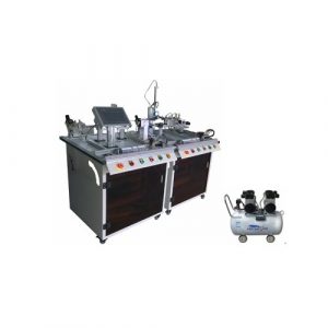
SR-MPS800 Mechatronics Trainer Vocational Training Equipment
SR-MPS800 Mechatronics Trainer Vocational Training Equipment. Jinan Should Shine Didactic Equipment Co., Ltd. is company specialized in manufacture and trading Engineering Educational Equipment,Technical Teaching Equipment,Vocational Training Equipment,Didactic Equipment for university,college,technical institution, polytechnics.Should Shine products has been exported to America,Asia,Europe,Africa, Australia.
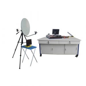
ZM5103 Satellite Trainer Educational Training Equipment
ZM5103 Satellite Trainer Educational Training Equipment. Jinan Should Shine Didactic Equipment Co., Ltd. is company specialized in manufacture and trading Engineering Educational Equipment,Technical Teaching Equipment,Vocational Training Equipment,Didactic Equipment for university,college,technical institution, polytechnics.Should Shine products has been exported to America,Asia,Europe,Africa, Australia.
ZM3106 Industrial Automation Trainer Mechatronics Training Equipment
ZM3106 Industrial Automation Trainer Mechatronics Training Equipment. Jinan Should Shine Didactic Equipment Co., Ltd. is company specialized in manufacture and trading Engineering Educational Equipment,Technical Teaching Equipment,Vocational Training Equipment,Didactic Equipment for university,college,technical institution, polytechnics.Should Shine products has been exported to America,Asia,Europe,Africa, Australia.