


- Description
- Inquiry
F1-15 Bernoulli’s Apparatus Test Equipment Educational Lab Equipment Hydrodynamics Laboratory Equipment
1. Equipment introduction
1.1 Overview
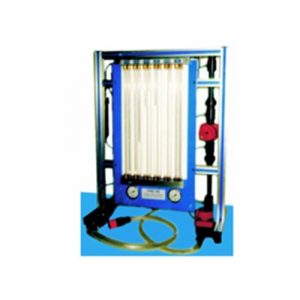
Venturi meters are a typical instrument used throughout industry. However, it has more pressure holes, connected to water pressure gauges, which allow the pressure distribution along the convergent-divergent channels to be fully studied. This equipment is used with gravity or volumetric hydraulic tables. Because these benches measure absolute flow, students can find the coefficients of the Venturi flowmeter under various flow conditions. The device consists of a horizontal venturi tube, downstream flow control valve and pressure gauge tube. The pressure gauge panel holds the pressure gauge tube vertically. The common manifold above the pipe has an air pressure control valve. The base has adjustable feet. The manometer panel has a scale behind the manometer tube for direct reading of the water level in the tube. Plastic materials and corrosion-resistant finishes throughout the unit prevent corrosion. Water enters the Venturi flowmeter and its flow control valve sets the flow rate. The valve is located downstream so it does not cause any upstream turbulence. To adjust the baseline water level in the manometer tube, students connect a hand pump (included) to the air pressure control valve above the manometer tube. To conduct the experiment, students set up and measured the flow rate through a venturi tube. They measure the head on the cross-sectional area of the upstream section and the head on the throat. They also noted the pressure distribution along the rest of the gauge. They then repeated the process, incrementally reducing the flow rate and taking similar readings each time. Students can compare ideal pressure distributions to measured pressure distributions and calculate discharge coefficients for flow meters.
1.2 Features
- The base adopts a sheet metal frame structure, which is durable and mobile.
- The equipment components are made of PVC pipes and stainless steel, and the ball valves are made of pure copper ball core.
2. Technical parameters
Size: 700mm*350*550mm
Weight: 25kg
Pressure gauge range: 0-300mm
Number of pressure gauge tubes: 8
Throat diameter: 10.0mm
Upstream diameter: 25.0mm
Upstream taper: 14°
Downstream taper: 21°
3. Components list and detailed introduction
3.1 Main part:
| No | Name |
| 1 | Vent |
| 2 | pitot tube |
| 3 | Silk screen scale |
| 4 | Venturi tube |
| 5 | water intake |
| 6 | Outlet |
| 7 | ball valve |
4. Experiment list
Experiment 1 Bernoulli equation experiment
Experiment 2 Venturi tube size and pressure tube position flow experiment
Experiment 3 Venturi Effect
Experiment 4 Verification of Bernoulli’s Ideal Fluid
Related Products
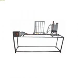
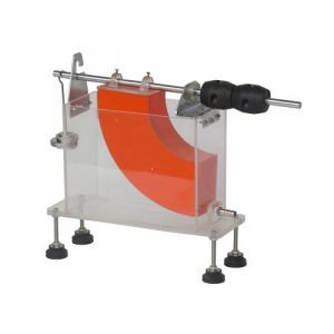
ZM7101 Energy Losses in Bends Educational Equipment
ZM7101 Energy Losses in Bends Educational Equipment. Jinan Should Shine Didactic Equipment Co., Ltd. is company specialized in manufacture and trading Vocational Training Equipment,Didactic Equipment,Engineering Educational Equipment,Technical Teaching Equipment,for university,college,technical institution, polytechnics.Should Shine products has been exported to America,Asia,Europe,Africa, Australia.
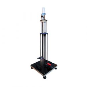
ZM7111A Bernoulli’s Principle Demonstration Apparatus Teaching Equipment
ZM7111A Bernoulli’s Principle Demonstration Apparatus Teaching Equipment. Jinan Should Shine Didactic Equipment Co., Ltd. is company specialized in manufacture and trading Vocational Training Equipment,Didactic Equipment,Engineering Educational Equipment,Technical Teaching Equipment,for university,college,technical institution, polytechnics.Should Shine products has been exported to America,Asia,Europe,Africa, Australia.
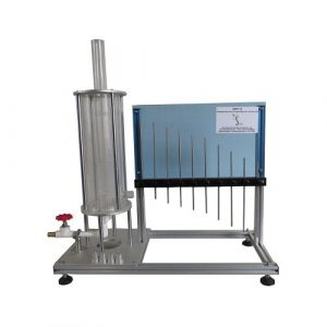
ZM7112 Measurement of Jet Forces Technical Teaching Equipment
ZM7112 Measurement of Jet Forces Technical Teaching Equipment. Jinan Should Shine Didactic Equipment Co., Ltd. is company specialized in manufacture and trading Vocational Training Equipment,Didactic Equipment,Engineering Educational Equipment,Technical Teaching Equipment,for university,college,technical institution, polytechnics.Should Shine products has been exported to America,Asia,Europe,Africa, Australia.
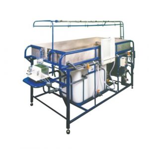
SR-S13 Advanced Hydrology Trainer Vocational Training Equipment
SR-S13 Advanced Hydrology Trainer Vocational Training Equipment. Jinan Should Shine Didactic Equipment Co., Ltd. is company specialized in manufacture and trading Vocational Training Equipment,Didactic Equipment,Engineering Educational Equipment,Technical Teaching Equipment,for university,college,technical institution, polytechnics.Should Shine products has been exported to America,Asia,Europe,Africa, Australia.
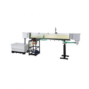
ZM7103 Hydraulics Bench with Pump Educational Equipment
ZM7103 Hydraulics Bench with Pump Educational Equipment. Jinan Should Shine Didactic Equipment Co., Ltd. is company specialized in manufacture and trading Vocational Training Equipment,Didactic Equipment,Engineering Educational Equipment,Technical Teaching Equipment,for university,college,technical institution, polytechnics.Should Shine products has been exported to America,Asia,Europe,Africa, Australia.
ZM7110A Osborne Reynolds Apparatus Educational Equipment
ZM7110A Osborne Reynolds Apparatus Educational Equipment. Jinan Should Shine Didactic Equipment Co., Ltd. is company specialized in manufacture and trading Vocational Training Equipment,Didactic Equipment,Engineering Educational Equipment,Technical Teaching Equipment,for university,college,technical institution, polytechnics.Should Shine products has been exported to America,Asia,Europe,Africa, Australia.
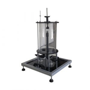
ZM7109 Hydrostatic Pressure in Liquids Educational Equipment
ZM7109 Hydrostatic Pressure in Liquids Educational Equipment. Jinan Should Shine Didactic Equipment Co., Ltd. is company specialized in manufacture and trading Vocational Training Equipment,Didactic Equipment,Engineering Educational Equipment,Technical Teaching Equipment,for university,college,technical institution, polytechnics.Should Shine products has been exported to America,Asia,Europe,Africa, Australia.
ZM7113 Horizontal Flow From A Tank Didactic Equipment
ZM7113 Horizontal Flow From A Tank Didactic Equipment. Jinan Should Shine Didactic Equipment Co., Ltd. is company specialized in manufacture and trading Vocational Training Equipment,Didactic Equipment,Engineering Educational Equipment,Technical Teaching Equipment,for university,college,technical institution, polytechnics.Should Shine products has been exported to America,Asia,Europe,Africa, Australia.
ZM8102 Ion Exchange Device Vocational Training Equipment
ZM8102 Ion Exchange Device Vocational Training Equipment. Jinan Should Shine Didactic Equipment Co., Ltd. is company specialized in manufacture and trading Vocational Training Equipment,Didactic Equipment,Engineering Educational Equipment,Technical Teaching Equipment,for university,college,technical institution, polytechnics.Should Shine products has been exported to America,Asia,Europe,Africa, Australia.
ZM7111B Bernoulli’s Teaching Equipment Fluid Mechanics Lab
ZM7111B Bernoulli’s Teaching Equipment Fluid Mechanics Lab. Jinan Should Shine Didactic Equipment Co., Ltd. is company specialized in manufacture and trading Vocational Training Equipment,Didactic Equipment,Engineering Educational Equipment,Technical Teaching Equipment,for university,college,technical institution, polytechnics.Should Shine products has been exported to America,Asia,Europe,Africa, Australia.